Rotary Engine Wiring 47
© 2009 Link
9.1 Rotary Injection Wiring
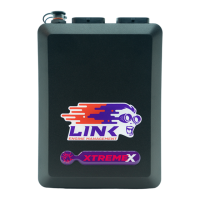
Wire Injectors as shown in the table below:
Inj 1 = Pri 1
Inj 2 = Pri 2
Inj 3 = Sec 1
Inj 4 = Sec 2
Inj 1 = Pri 1
Inj 2 = Pri 2
Inj 3 = Pri 3
Inj 4 = Sec 1
Inj 5 = Sec 2
Inj 6 = Sec 3
Inj 1 = Pri 1
Inj 2 = Pri 2
Inj 3 = Pri 3
Inj 4 = Pri 4
Inj 5 = Sec 1
Inj 6 = Sec 2
Inj 7 = Sec 3
Inj 8 = Sec 4
Rotary Injection Wiring
Notes:
· A Xtreme ECU is required for sequential injection on 3 and 4 rotor engines.
· Injection mode should be set to Sequential/Staged.
· Ensure injector staging adjustments and primary and secondary injector dead times
are is setup correctly for the injector types fitted.
· Storm ECU's must be wired with ballast resistors if low impedance injectros are used.
· When wiring low impedance injectors directly to a Xtreme ECU make sure Injector
Driver Mode is set to Peak and Hold and the correct peak and hold currents have
been set.
· Spare Injection drives can be used as additional auxiliary outputs if required.
9.2 Rotary Ignition Wiring
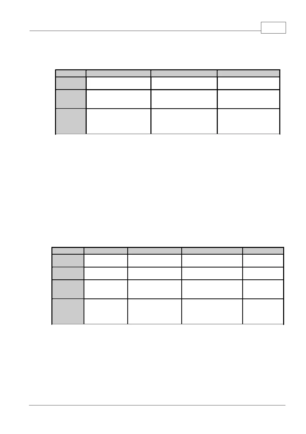
Wire Ignition as shown in the following table:
Ign 1 = L1
Ign 2 = L2
Ign 3 = L3
Ign 4 = T1
Ign 5 = T2
Ign 6 = T3
Ign 1 = L1
Ign 2 = L2
Ign 3 = L3
Ign 4 = L4
Ign 5 = T1
Ign 6 = T2
Ign 7 = T3
Ign 8 = T4
Rotary Ignition Wiring
Notes:
· A Xtreme ECU is required for direct spark ignition on 3 and 4 rotor engines.
· Ensure the Ignition Mode is set to Rotary – Direct or Rotary – Leading Wasted. Do
not use the generic Direct Spark or Wasted Spark modes.
· Igniters must be wired. Do not wire coils directly to the ECU.
· Spare Ignition drives can be used as additional auxiliary outputs if required.