G4 Wiring and Installation Manual44
© 2009 Link
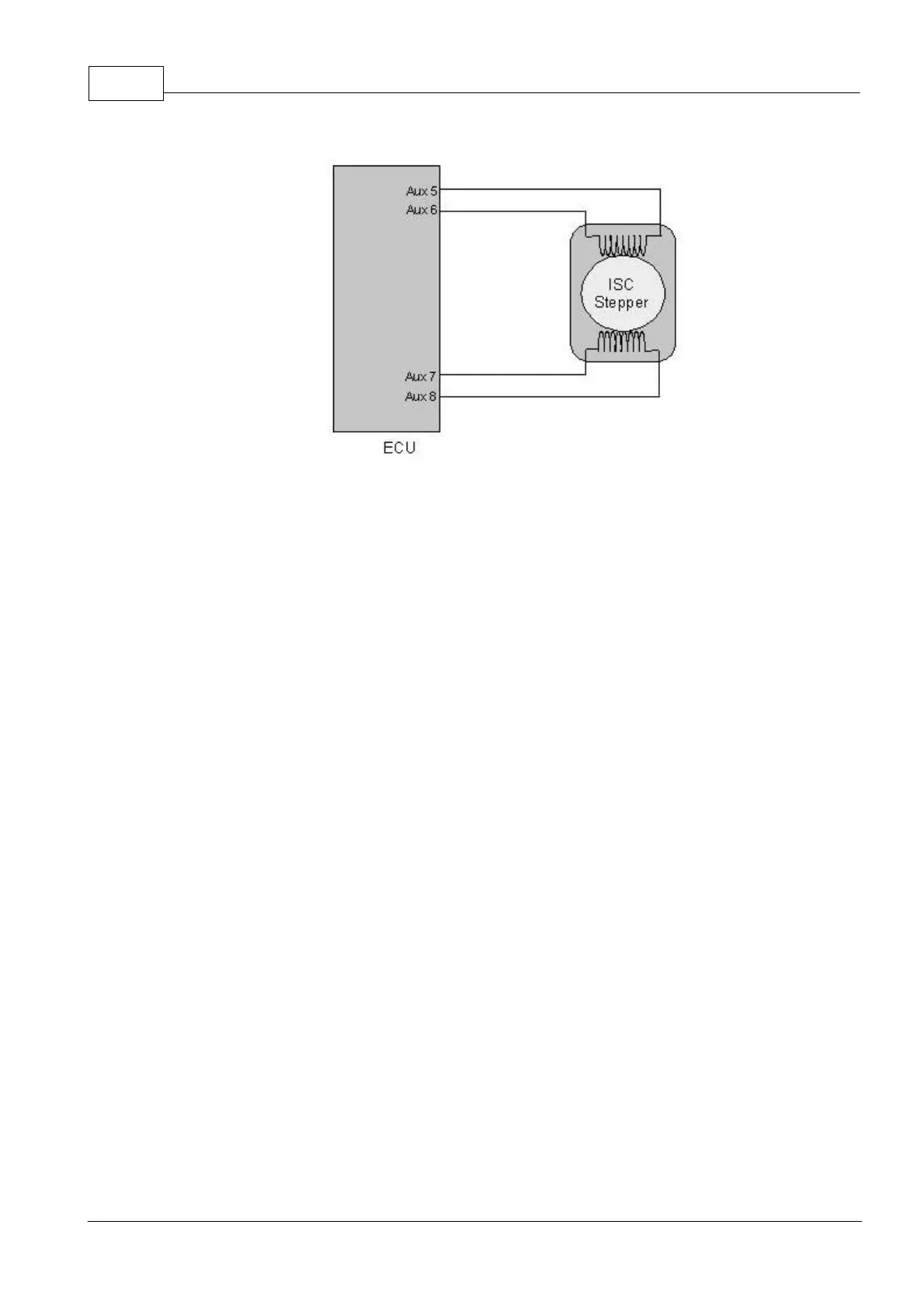
Four-terminal ISC Stepper Motor
8.4.4 Six Terminal ISC Stepper Motor
An ISC Stepper Motor must be wired to Aux 5, Aux 6, Aux 7 and Aux 8.
When using an ISC Stepper, the ECUs power supply should be wired for ECU Hold Power.
This will allow the ECUs Hold Power function to be taken advantage of. Using ECU Hold
Power allows the ECU to reset the stepper motor after key off. This avoids extended
cranking periods caused by resetting the stepper at key on.
The diagram below shows a schematic of a six-terminal stepper motor. These are similar to
a four-terminal Stepper Motor, but each coil has a centre-tap that must be connected to 12V.
Like the four-terminal version, Aux 5 and 6 must be connected to the terminals for one coil,
while Aux 7 and 8 must be connected to the terminals for the other coil. If it is found that the
stepper motor runs in the opposite direction to that expected, reverse the wiring to Aux 5
and Aux 6 channels.