EasyManua.ls Logo

Link G4 Storm - Installer IO Table

Link G4 Storm
63 pages
Print Icon
To Next Page IconTo Next Page
To Previous Page IconTo Previous Page
Loading...
G4 Wiring and Installation Manual10
© 2009 Link
Example of usage of inputs and outputs
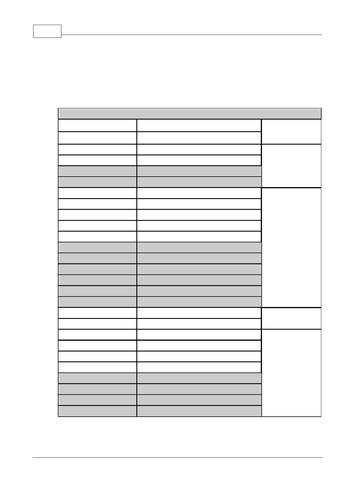
2.8 Installer IO Table
Fill out the following table to assist in installation. It will come in useful when configuring
inputs and outputs in PCLink Tuning Software. Shaded areas indicate I/O only available on
Xtreme ECU's.
Configuration: 6 Cylinder, direct spark, sequential injection, turbocharged
Trigger 1
Crank Angle Sensor
Reluctor,
Proximity, Optical
or Hall
Trigger 2
Analogue Temp Input 1
NTC Thermistor
sensors Only
Analogue Temp Input 2
Analogue Temp Input 3
Analogue Temp Input 4
Analogue Volt 1
0-5V Input from
sensor or external
controller
Analogue Volt 2
(Shared with DI4 on Storm)
Analogue Volt 3
Analogue Volt 4
Analogue Volt 5
(Internal MAP on Storm)
Analogue Volt 6
Analogue Volt 7
Analogue Volt 8
Analogue Volt 9
Analogue Volt 10
Analogue Volt 11
+5V Out
TPS and MAP sensor power
+5V Power OUT
+8V Out
Ignition 1
Use spare Ignition
channels for
switching type
Auxiliary Outputs
Ignition 2
Ignition 3
Ignition 4
Ignition 5
Ignition 6
Ignition 7
Ignition 8

Table of Contents