G4 Wiring and Installation Manual24
© 2009 Link
7.3 TPS Wiring
A Throttle Position Sensor (TPS) is connected directly to the end of the throttle shaft to
measure the current angle of throttle opening. Even if the throttle position sensor is not
required for load sensing, it is still highly recommended to use one. Throttle position is used
for a number of other functions including:
· Acceleration enrichment (much better than using MAP)
· Overrun fuel cuts
· Idle Speed Control
· Boost Control (in some cases)
· Anti-Lag
The throttle position sensor must be a potentiometer (variable
resistance) and operate over the entire range of throttle movement.
Partial range sensors and idle/full-throttle switches are not suitable
and may not be used with G4 ECU's.
Ensure the TPS mounting position allows the throttle to move through its full range of
motion. The TPS should be adjusted so that it is not reaching the end of its movement at
either closed throttle or full throttle. An ideal output voltage range is 0.5 to 4.5 volts. Note:
that the ECU will interpret a 0V or 5V signal on the TPS channel to be an error condition.
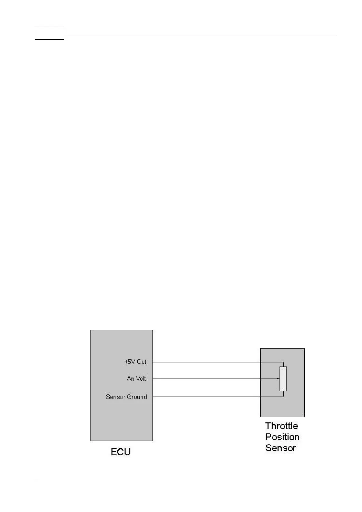
A typical TPS has 3 terminals. To wire either the factory TPS or a custom fitted sensor, an
ohmmeter is required. Two of the terminals will show a fixed resistance as the TPS is
moved. Connect these terminals to the +5V Out wire (Red/Blue) and Sensor Ground wire
(Green). The orientation of the +5V and ground does not matter. The result is that the TPS
output will either increase or decrease in voltage with throttle position. The ECU will
automatically detect this so either option is acceptable. The third terminal must show a
variable resistance between it and the ground terminal as the throttle position is changed.
This is the TPS output and should be connected to any Analogue Volt input.