LinRS Interface
2 Connecting the RS bus
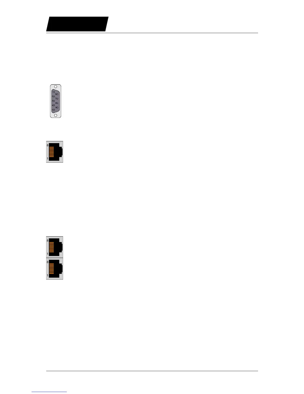
2.1 Pin Out of the COM Connector (X5) (E1100, B1100-GP)
Over this connector the RS232 or the RS422/RS485 serial lines are available.
Pin 1 RS-485 Tx+ Pin 6 RS-485 Rx-
Pin 2 RS-232 TX Pin 7 RS-485 Tx-
Pin 3 RS-232 RX Pin 8 CAN L
Pin 4 RS-485 Rx+ Pin 9 CAN H
Pin 5 GND (100)
2.2 Pin Out of the System Connector (X19) (E1200-GP, E1400-GP)
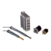
2.3 Pin Out of the CMD Connector (X7, X8):
The CMD connector exists on the series E1100 (except E1100-GP), B1100-GP, E1200-GP,
C1100-GP, and E1400-GP drives, 2xRJ45 with 1:1 connected signals. Standard twisted
pairs: 1/2, 3/6, 4/5, 7/8. Use Ethernet cables according the EIA / TIA 568A standard.
Page 6/59 User Manual LinRS Interface / 03/10/2017 NTI AG / LinMot