20
Servicing the Drive Components
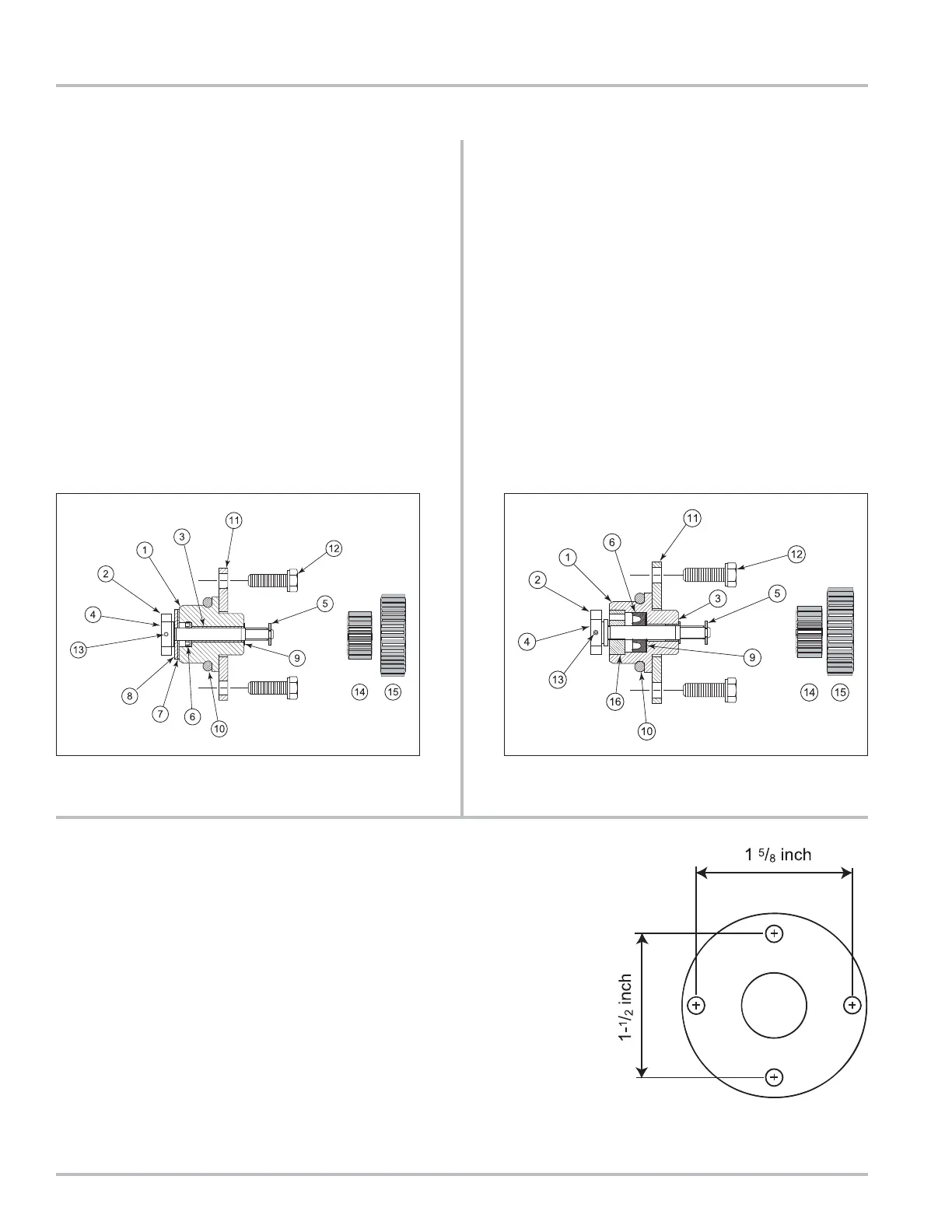
The Retaining Plate
The retaining plate has four holes”
Two that are drilled 1.5” on center
Two that are drilled 1.625” on center.
Turn the retaining plate until the holes match up with the
threads to determine which orientation is correct for the
meter being serviced.
1. Housing
2. Drive Blade
3. Bushing
4. Shaft
5. Retaining Clip
6. “U” Cup
7. Rulon Thrust Washer
8. Stainless Steel Thrust Washer
9. Nylon Washer
10. O-Ring
11. Retaining Plate
12. Retaining Plate Screws (2)
13. Roll Pin
14. Output Gear 1:2
15. Output Gear 1:1
1. Housing
2. Drive Blade
3. Bushing
4. Shaft
5. Retaining Clip
6. “U” Cup
9. Stainless Steel Washer
10. O-Ring
11. Retaining Plate
12. Retaining Plate Screws (2)
13. Roll Pin
14. Output Gear 1:2
15. Output Gear 1:1
16. Carbon Guide Bearing
Standard Packing Gland LPG Packing Gland