21
Disassembling the Meter
(See Pages 31 & 32 for the Torque and Wrench & Socket Size Charts)
All internal pressures must be relieved before disassembly of the meter, strainer, vapor eliminator,
any valves in the system, the pulse output device, or the front and rear covers. LINE PRESSURE
MUST BE 0.0 PSI. See “Meter Maintenance” on Page 15 for the procedures to relieve internal
pressure.
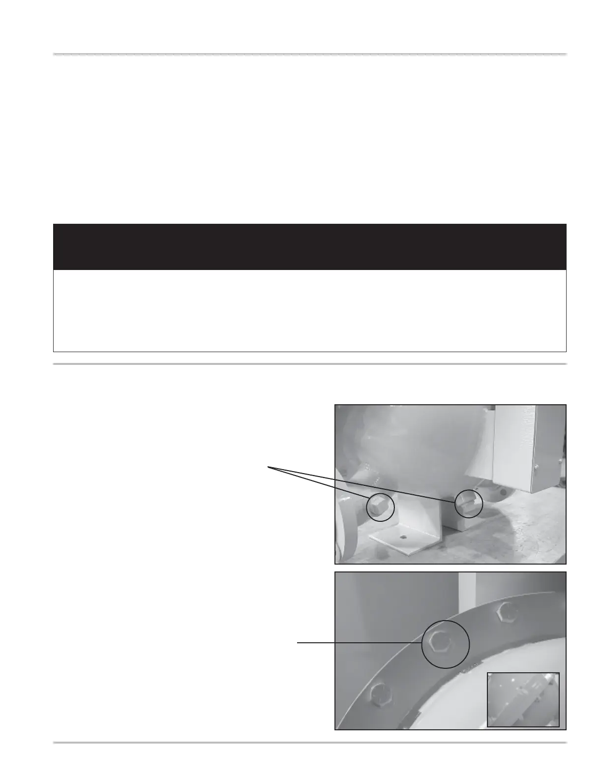
1. After the internal pressure has be relieved, open the
drain plugs located at the bottom of the weldment
assembly and discharge arm to drain all fluid from
the weldment assembly.
Draining Fluid from the Meter
2. Once the system has been completely drained, the
weldment assembly may be opened by removing the
cover screws and bolts that are located around the
rim of the enclosure.
The number of bolts may vary between the different
meter sizes.
Opening the Weldment Assembly
Tools:
Torque Chart
Wrench & Socket Size Chart
Counter bracket wrench or socket
Drain plug wrench
Cover socket or open end/box end wrench
Standard screwdrivers (2)
Spare displacement rotor gear
Bearing plate wrench
Plastic or rubber mallet
Emery cloth
Wire brush

 Loading...
