27
Reassembling the Meter
(See Pages 31 & 32 for the Torque and Wrench & Socket Size Charts)
NOTE: The principles of meter disassembly and
reassembly are the same for all Liquid Controls meters.
Although your meter may look slightly different than those
pictured, the steps are the same, except as noted.
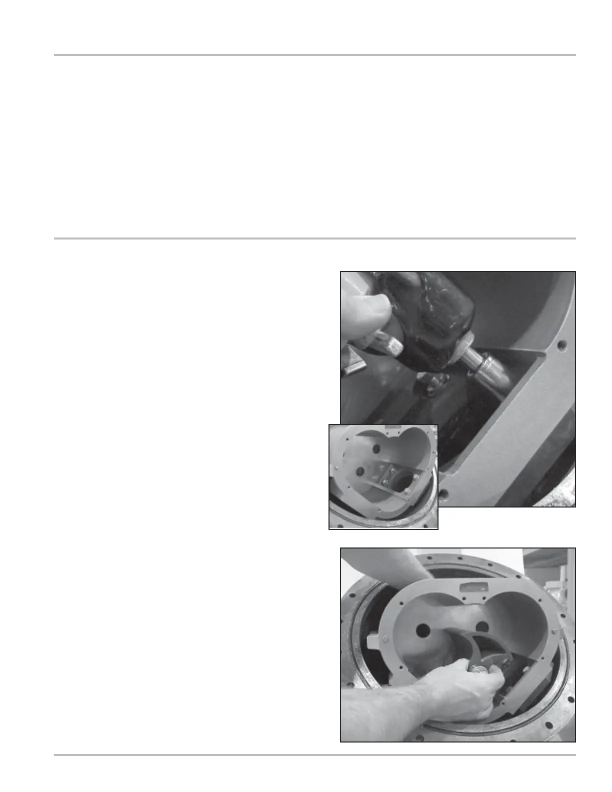
Installing the Meter
1. Place the flat gasket in the lower weldment and line
up the bolt holes. Position the meter housing in the
weldment lower hemisphere and secure using the
four bolts. Use care not to damage the flat gasket.
Use an impact driver or socket to tighten bolts.
2. Install the blocking rotor. It will be necessary to guide
the universal joint assembly into the drive coupling
bearing and packing gland by reaching behind the
meter element.
Assembling the Meter
Tools:
Cover socket or open end/box end wrench
Spare displacement rotor gear or shop rag
Rotor gear wrench or socket
Bearing plate wrench or socket