19
Servicing the Drive Components
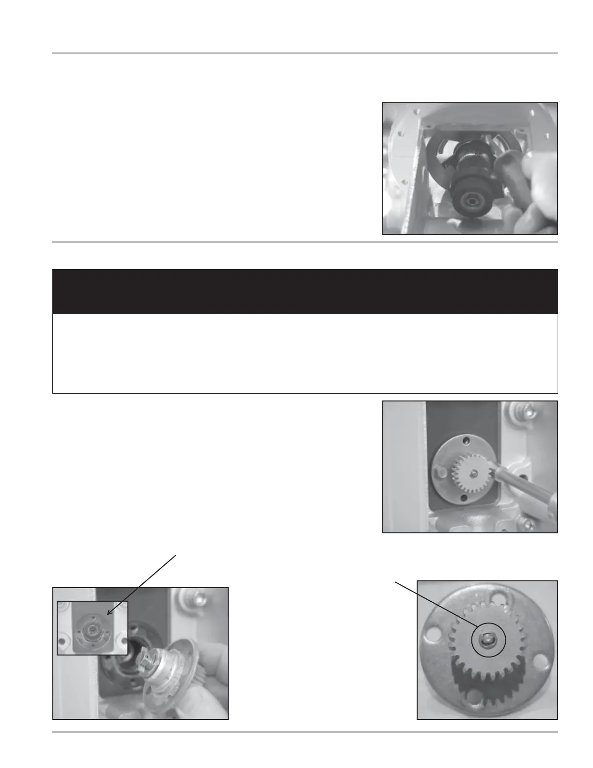
7. Remove the Adjuster assembly by removing the
single screw holding it in place. The adjuster can
then be rotated clockwise and removed from below.
Removing the Adjuster and Adjuster Drive Assembly (Continued)
Removing the Packing Gland
8. Remove the two packing gland retaining plate screws
with a 5/16” socket and ratchet driver extension or 5/
16” nut driver.
NOTE: It is not necessary to completely remove the
stack from the meter to service the packing gland.
9. Pull out the packing gland. There is an O-Ring for
the packing gland which may not come out with the
packing gland. If it does not come off with the packing
gland, it will be located in the packing gland well.
All internal pressures must be relieved before disassembly of the meter, strainer, vapor eliminator,
any valves in the system, the pulse output device, or the front and rear covers. LINE PRESSURE
MUST BE 0.0 PSI. See “Meter Maintenance” on Page 15 for the procedures to relieve internal
pressure.
The packing gland may be taken apart by removing
the retaining ring from the gear end of the assembly.