22
Disassembling the Meter
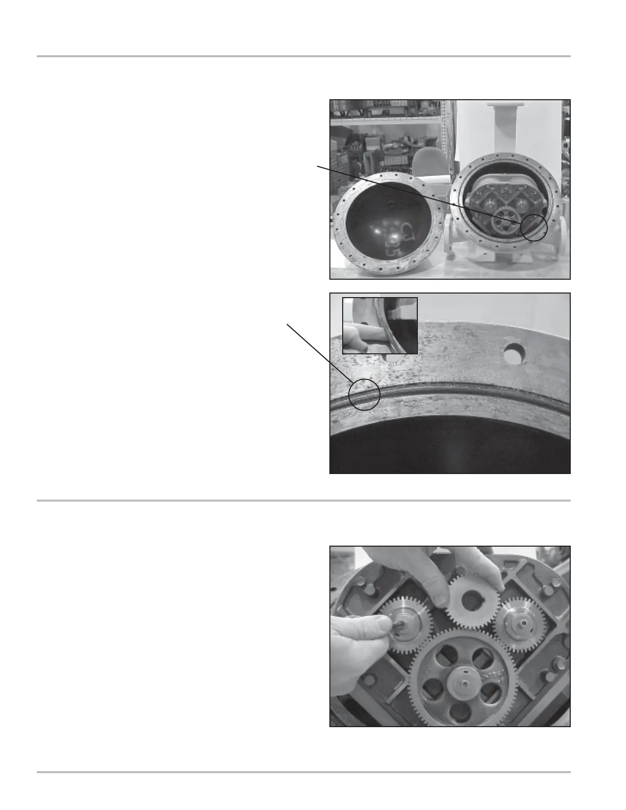
3. When all the screws and bolts have been removed,
remove the weldment cover. This exposes the inside
of the weldment assembly and provides access to
the meter assembly. The meter assembly is held in
place by 4 bolts on the inlet side of the meter. This
can be either side of the meter depending on the
direction of flow.
Access to these four bolts is gained by removing the
front bearing plate of the meter housing.
4. Remove the O-Ring from the weldment assembly.
Undamaged O-Rings may be reused.
5. Hold a spare displacement rotor gear between the
right displacement rotor gear and the blocking rotor
gear to keep them from turning. If a spare gear is
not available, use a shop rag between the gear teeth.
Use the rotor gear allen key to loosen the rotor gear
screw by turning it counter-clockwise. Do not remove
the screw completely.
NOTE: Do not use a metallic tool for locking the gears
as this will likely result in damage to the gear teeth.
Removing the Rotor Gears