SCP System • System description
CP_SEM_60-00-00.002 13
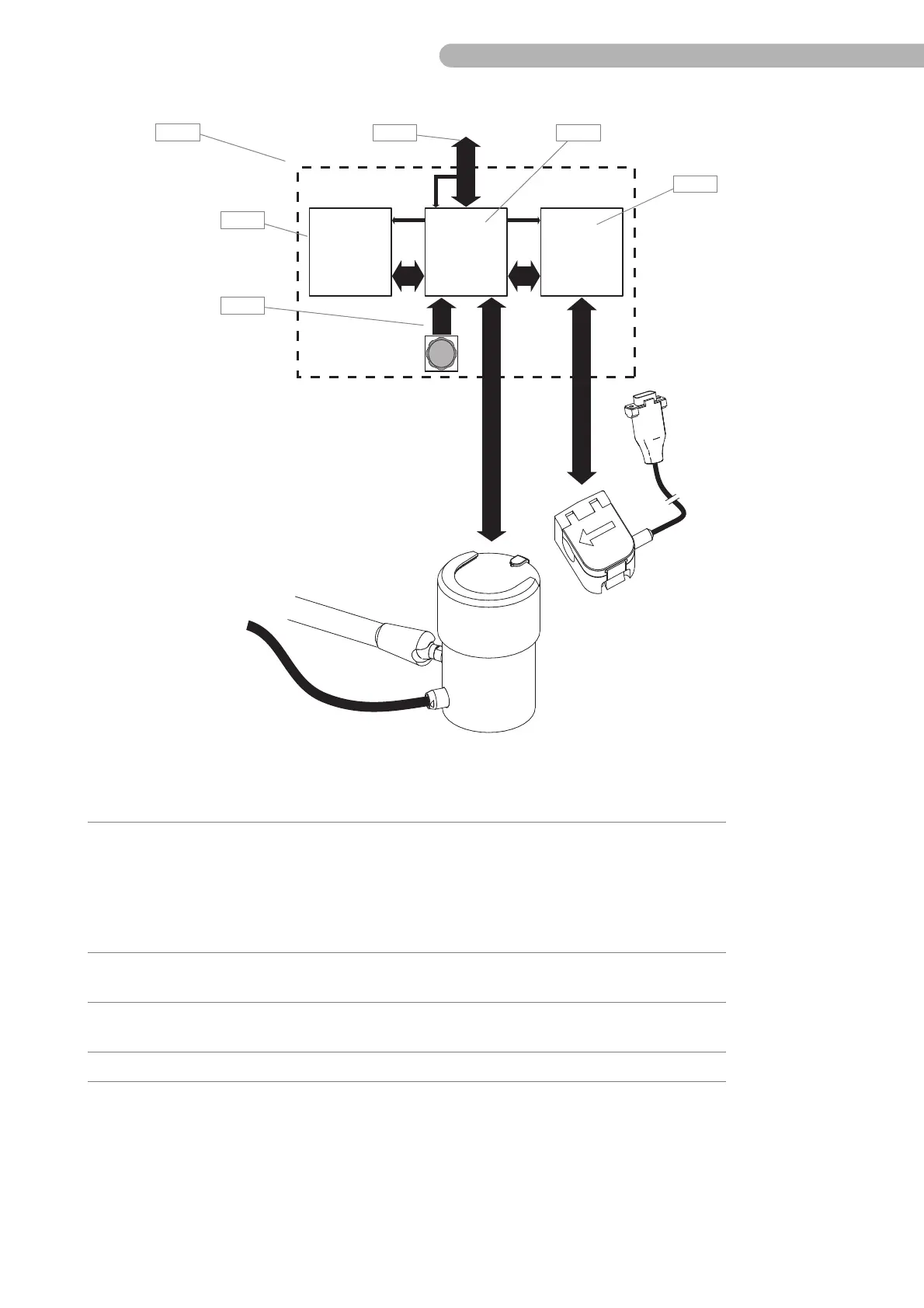
Fig. 2: Diagram of the SCP System
ZPA 9908 ZKR 9910 DIGIFLOW
24V
24V
5V
Mod. Components contains the following service-relevant modules/components:
A Pump control panel ◗ Display board ZPA 9908 (A 3)
◗ CPU board ZKR 9910 (A 4)
◗ Flow sensor board DIGIFLOW (A 5)
◗ Shaft angle encoder (A 2)
◗ Fan
◗ HLM/SCPC connecting cable (A 9)
See „Module overview
- Pump control panel“
on page 15.
B Drive unit ◗ Motor control board ZPR 9909 A
◗ Pump control panel connecting cable
C Emergency drive unit ◗ None. In the event of a defect, replace the emergency drive
unit.
D Flow sensor ◗ None. In the event of a defect, replace the flow sensor.