SCP System • Replacing components
38 CP_SEM_60-00-00.002
Assembling the shaft angle encoder
To assemble the shaft angle encoder you need:
– special mounting adapter for torque wrench (p/n 45-21-45)
– washer (p/n 60-02-04)
– a commercially available torque wrench with precision of ± 0.1 Nm
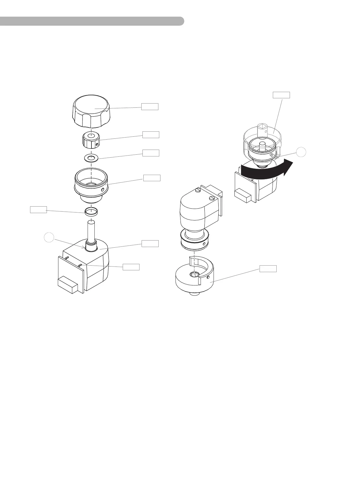
Fig. 23: Assembling the shaft angle encoder
◗ Use only tested shaft angle encoders (SAE) with a flat cable.
◗ Slide the washer A 48 over the shaft of the SAE and place it into the groove a.
◗ From below, put the SAE through the opening of the pump control panel and hold on to it. Make
sure that the SAE is seated correctly.
◗ Lightly screw the guide sleeve A 46 onto the SAE.
◗ Place the mounting adapter on the guide sleeve.
◗ Using the torque wrench, tighten the guide sleeve with a torque of maximum 1.5 ± 0.1 Nm.
◗ Slide the PA washer A 45 over the shaft of the SAE.
◗ Slide the mounting nut A 44 onto the shaft of the SAE until it touches the guide sleeve.
◗ Position the mounting nut A 44 with the two set screws b straight on the axis. Then check whether
the shaft can be easily and smoothly rotated in both directions.
◗ Put the rotary knob A 43 onto the mounting nut A 44, ensuring that the external sides (mounting
nut) and internal sides (rotary knob) correspond to one another.
◗ Check whether the rotary knob can be easily and smoothly rotated in both directions.
◗ Reconnect the connector A 33 to the CPU board.
b
A 43
A 44
A 46
A 47
A 48
A 45
A 49
A 49
a
A 33