Do you have a question about the LivaNova CP5 and is the answer not in the manual?
Provides basic information on the maintenance and repair of the CP5 system.
Explains the meaning of symbols used for safety instructions and text passages.
Overviews the manual's chapters and the information contained within each.
Lists standards and statutes the CP5 conforms to for service and operation.
Outlines regulations and general safety guidelines for CP5 operation and maintenance.
Provides essential safety guidelines for CP5 operation, maintenance, and handling.
Details critical safety precautions to be followed during the operation of the CP5 system.
Specifies mandatory electrical safety requirements for CP5 installation and operational use.
Outlines essential safety guidelines to be followed during routine maintenance procedures.
Provides specific safety advice and precautions for personnel performing service on the CP5.
Explains the integrated safety features and self-monitoring capabilities of the CP5.
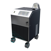
Offers a general overview of the CP5 system components and their fundamental functions.
Lists and briefly describes the primary constituent components of the CP5 system.
Illustrates the physical layout, connections, and main assemblies of the CP5 system.
Details which CP5 assemblies are serviceable on-site and their specific repair limitations.
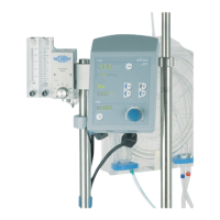
Provides a detailed breakdown of the individual components within the CP5 control panel.
Details the components, connections, and functions of the main computer circuit board.
Describes the specific circuit board housing the keys and LED indicators for the CP5.
Explains the circuit board responsible for the inversion functions within the CP5.
Details the circuit board dedicated to managing and controlling the system's fan.
Illustrates the physical components and structure of the CP5 drive unit.
Details the specific motor control circuit board (ZPR 0801) used in the drive unit.
Describes the flow sensor component and provides guidance on its replacement.
Explains the operational principles and functional diagram of the ultrasound flow probe.
Details the sensor module assembly and its constituent circuit boards.
Provides an overview of the icons and display elements found on the CP5 control panel.
Explains general key icons and display indicators present on the CP5 system panel.
Details specific icons and display elements used within the CP5 system menu interface.
Lists and describes various fault messages that can occur with the CP5 system.
Describes specific faults related to the sensor modules and individual sensors.
Instructions for accessing and replacing components within the CP5 pump control panel assembly.
Specific guidance on the procedures for replacing various components of the control panel.
Outlines the steps for safely removing and replacing circuit boards in the control panel.
Provides the procedure for removing and replacing the touch screen interface.
Details the steps required for safely removing the shaft encoder component.
General information and instructions for opening and accessing the CP5 drive unit.
Instructions for replacing specific components, such as the motor control board, in the drive unit.
Procedure for unplugging, removing, and replacing the connecting cable of the drive unit.
General guidance for replacing circuit boards within the sensor module assembly.
Details on FCI plug connectors, including their configuration and terminal assignments.
Provides configuration details and pin assignments for RIA plug connectors.
Illustrates the physical appearance and types of Phoenix plug and socket connectors used.
Shows the configurations and types of AMP plug and socket connectors utilized.
Provides detailed dimensions, weights, and operating conditions for CP5 system components.
Details crucial electrical parameters and specifications for the CP5 system.
Lists general specifications such as drip-proof rating, pump accuracy, and display resolution.
Explains the meaning and usage of various icons found on the pump control panel and sensor module.
Lists the official part numbers for CP5 system components and related accessories.
Information regarding approved accessories that can be used with the CP5 system.
States that the device is covered by contractually agreed warranty conditions.
Lists specific part numbers for components intended for service technicians.
Lists part numbers for components related to the drive unit and emergency system.
Lists part numbers for sensor module assembly materials and individual components.
Provides essential wiring diagrams illustrating the connections within the CP5 pump control panel.
| Device Type | Heart-Lung Machine |
|---|---|
| Manufacturer | LivaNova |
| Model | CP5 |
| Application | Cardiopulmonary Bypass |
| Power Supply | 100-240 VAC, 50/60 Hz |
| Display | Touchscreen LCD |
| Safety Features | Air bubble detection, Pressure monitoring |