SCP System • Error messages and error diagnosis
CP_SEM_60-00-00.002 25
4 Error messages and error diagnosis
The SCP System is subjected to continual monitoring. Errors that occur (e.g. a component breaks
down) are displayed as E(rror) codes on the 7-segment displays.
4.1 Error messages
4.1.1 Non-specific error displays and operating errors
Error Description/Possible causes Corrective measures
(please observe sequence)
Display is
dark
HLM/SCPC connecting cable defective – Check/replace connecting cable
see page 35
Switch defective – Check/replace switch
Mains filter defective – Check/replace mains filter
see page 35
Contact error (CPU board, CON 3) – Test connector between CPU board and
display board, clean contacts
– If the plug contacts are bent or broken,
replace display board
– If the socket contacts are broken or
corroded, replace CPU board
Display board (ZPA 9908) defective – Replace display board
see page 33
CPU board (ZPA 9910) defective – Replace CPU board
see page 32
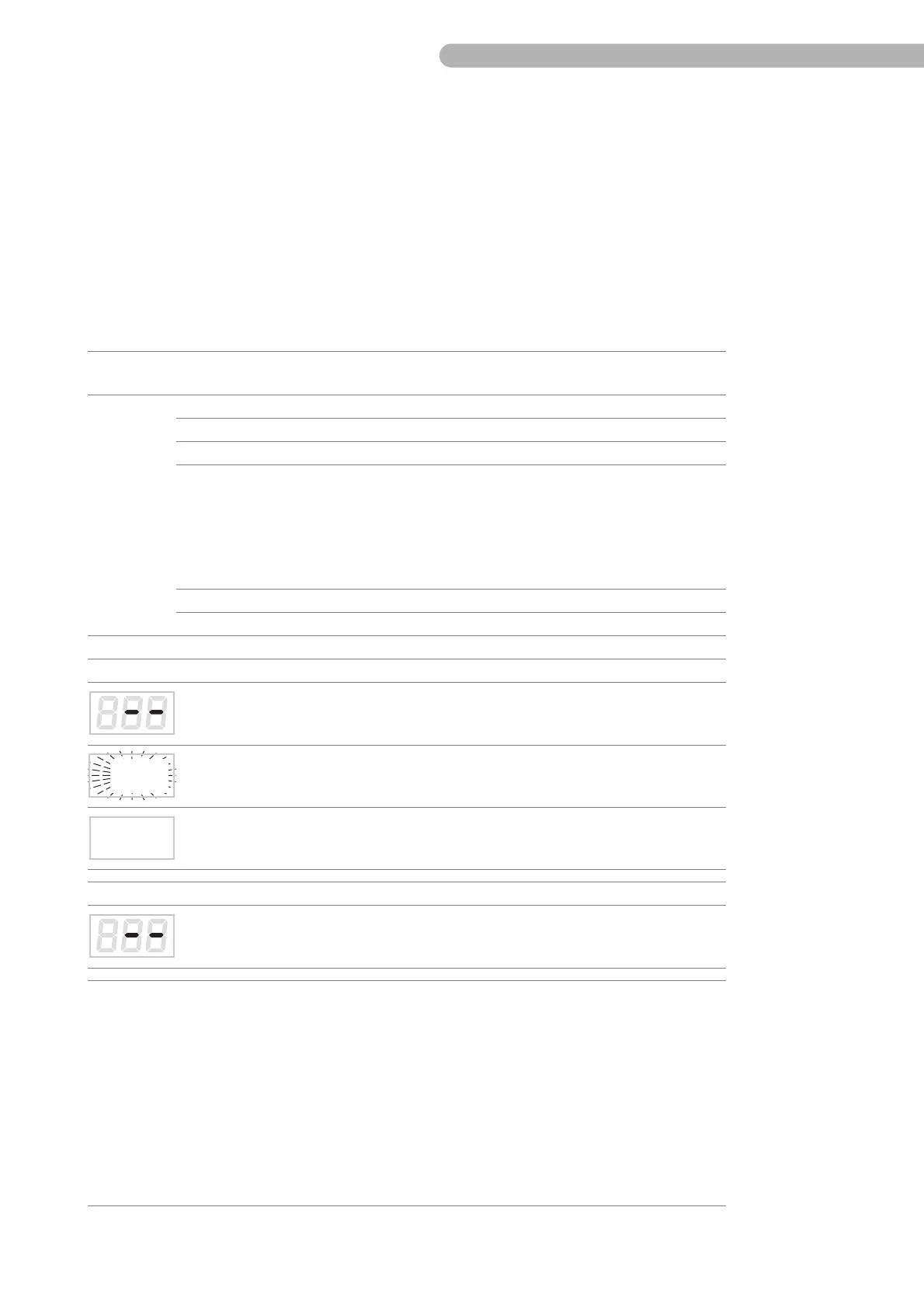
7-segment display “Flow”
Flow sensor not correctly connected or
defective
– Test flow sensor connection
– Replace flow sensor
Processor error (display flashes rapidly
during operation)
–Replace CPU board
see page 32
Display not “0.00” even though arterial
line is clamped (operating error)
– Perform zero calibration according to
operating instructions
7-segment display “Pressure”
No pressure control has been assigned
(operating error)
– Assign the pressure control according
to operating instructions
Incorrect pump no. (S3, SC, S5, C5,) or no
display (SCPC)
– With S3/SC/S5/C5 the SCP is displayed
as pump no. 6. However, with S5 and
C5 the initial pump number 6 can be
modified.
– No connection to SCPC.
Check the position of S1 on the CPU board
ZKR 9910:
– For S3, SC, or SCPC the S1 switch must
be OFF.
– For S5 and C5 the S1 switch must be ON.
see page 29