SCP System • Replacing components
CP_SEM_60-00-00.002 33
Display board (ZPA 9908)
Removal of the display board is necessary in the following cases:
◗ For replacement in the event of defective keys, LEDs or 7-segment displays
◗ For replacement in the event of a relevant error message (E08)
◗ For replacement in the event of a defective fan
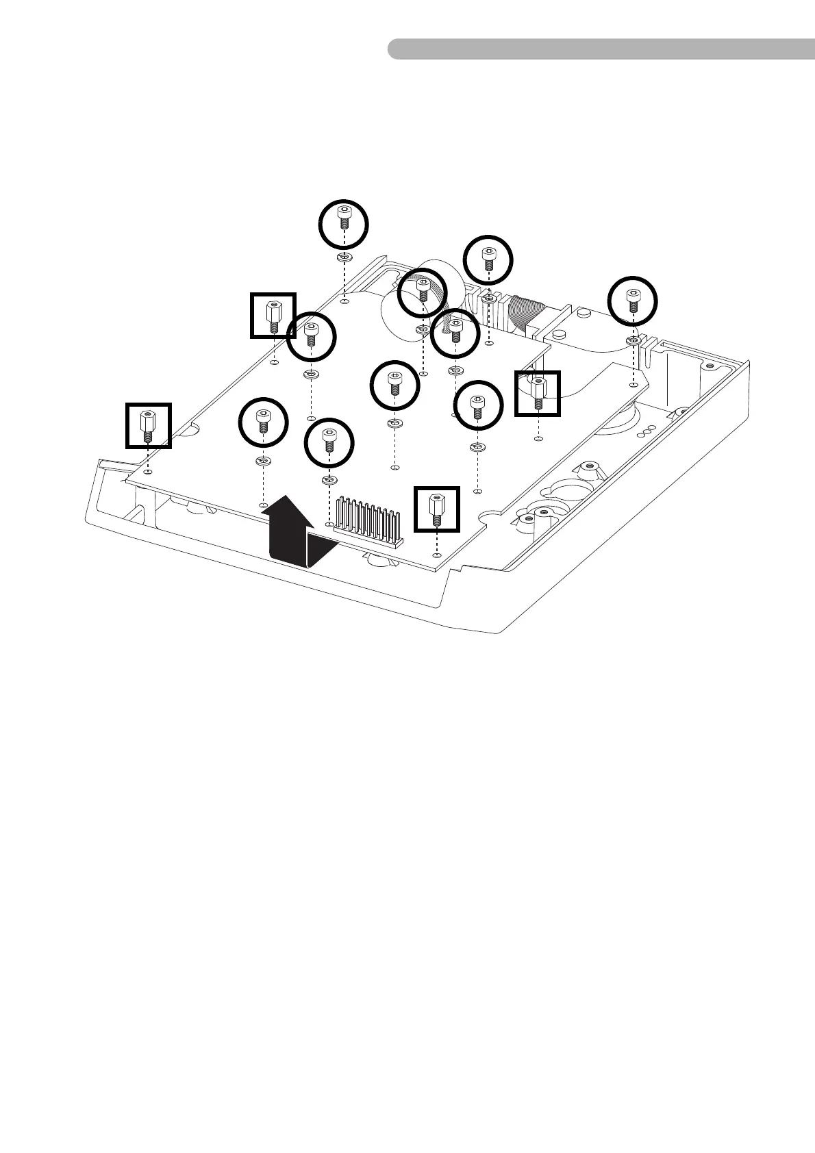
Fig. 16: Dismantling the CPU board
◗ Unscrew the ten screws indicated (Allen key 2.5) including the washers.
◗ Loosen the four mounting bolts indicated
◗ Pull out the board carefully
➜ first from underneath the shaft angle encoder and
➜ then upwards (see arrow in top diagram).
Then replace the board in the opposite order.
Note that the display board is part of a spare part kit (p/n 003-20-001) which also includes 6 pusher
caps. Previous versions of the display board can still be used; use the pusher caps from the display
board you are replacing. The old pusher caps do not fit on the current version of the display board.