Chapter 2 System Configuration
Items Items Items
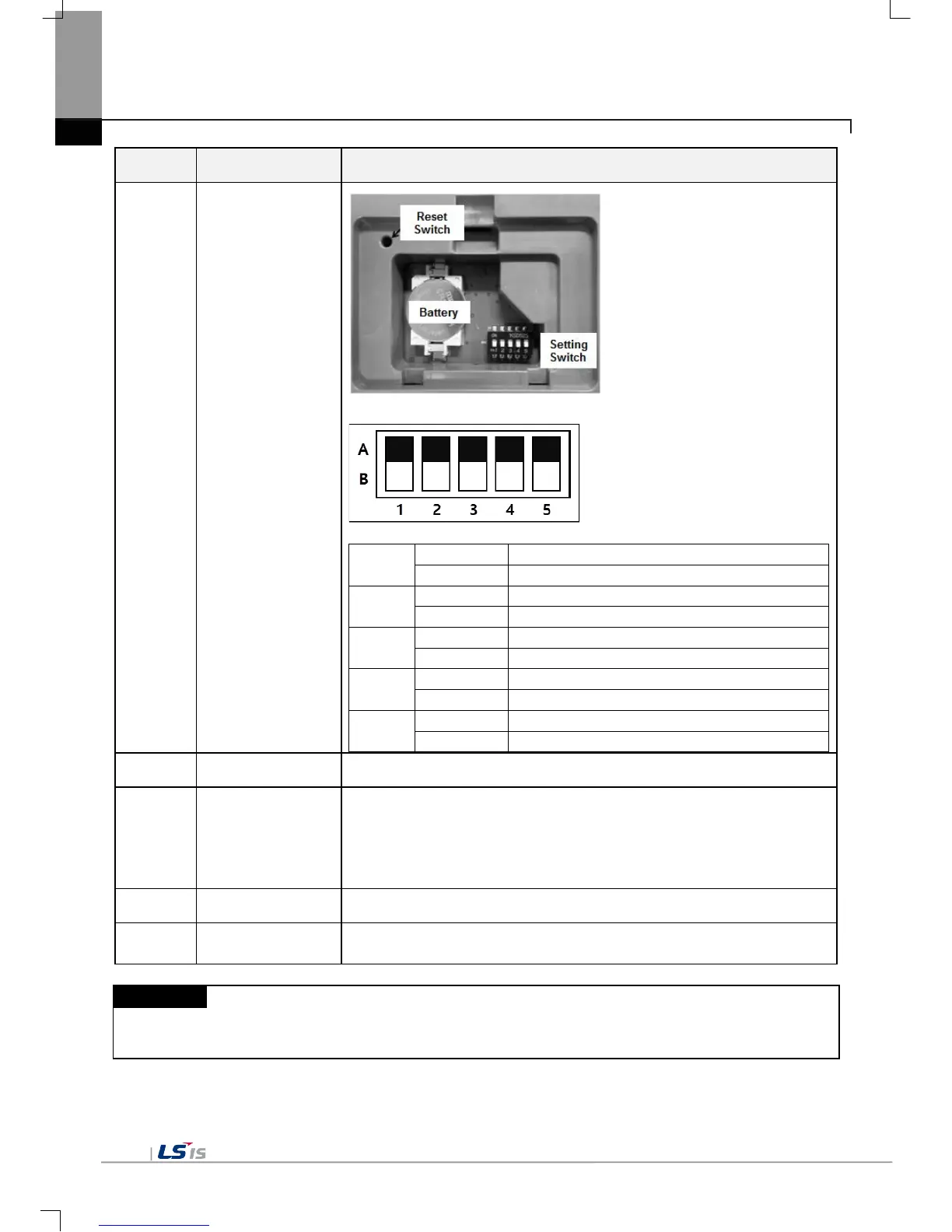
⑥
Battery Cover
<Setting Switch Configuration >
NO.1
COM1 RS-485 Terminating Resistance On
COM1 RS-485 Terminating Resistance Off
COM3 RS-422 Terminating Resistance On
COM3 RS-422 Terminating Resistance Off
⑦
Power Terminal Composed of Power Input(DC24V) and FG Terminal
⑧
Ethernet Terminal
Ethernet: 10Base-T/ 100Base-TX
1) Send Project Data
2) Receive backup data and project file
3) Send XP-Runtime
4) PLC/Control Device Communication
⑨
COM3 Connector RS-422/485: PLC or Control Device Communication
⑩
RS-485, RS-232C: PLC or Control Device Communication
(1) For further details on connection of communication, please refer to Communication Instruction Manual.
(2) For further details on installation, please refer to the Chapter 10.
B. Coin Battery
C. Setting Switch
 Loading...