Chap. 6 Analog I/O Module (XBF-AH04A)
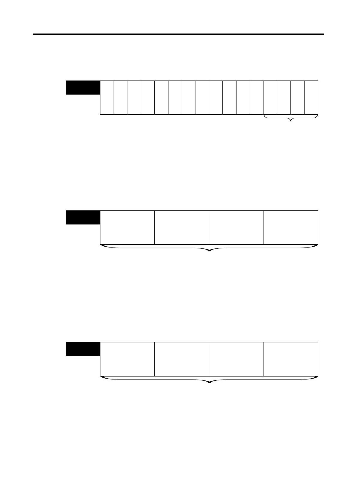
(1) Operating Channel Setting
The default setting for operating channel is ‘Stop.’
Bit15 Bit14 Bit13 Bit12
Bit11 Bit10
Bit9 Bit8
Bit7 Bit6
Bit5
Bit4 Bit3
Bit2 Bit1 Bit0
O
u
t
p
u
t
C
H
.
1
O
u
t
p
u
t
C
H
.
0
I
n
p
u
t
C
H
.
1
I
n
p
u
t
C
H
.
0
--
--
--
Address0
Appoint Using CH. bit
Bit On (1): Operate
Bit Off (0): Stop
-
--
- --
(2) I/O Range Setting
(a) The analog I/O voltage range is DC 1~5V, DC 0~5V, DC 0~10V, and analog current I/O
range is DC 4~20mA, DC 0~20mA.
(b) Default range is DC 4~20mA.
Bit15
Bit14
Bit13
Bit12
Bit11
Bit10 Bit9 Bit8
Bit7 Bit6 Bit5
Bit4
Bit3
Bit2
Bit1
Bit0
Input CH.0
Address1
Input ch. Set-up I/O range(by ch. 4bit)
0 : 4 ~ 20 ㎃
1 : 0 ~ 20 ㎃
2 : 1 ~ 5 V
3 : 0 ~ 5 V
4 : 0 ~ 10 V
Input CH.1Output CH.0Output CH.1
(3) I/O Data Type Setting
(a) I/O data type can be set up for each channel.
(b) If the I/O data type is not set up, all the channels are processed in 0~4000 range.
bit15 bit14 bit13
bit12
bit11 bit10
bit9
bit8 bit7 bit6
bit5
bit4
bit3 bit2 bit1 bit0
Input CH. 0
Address2
Set-up I/O data type (by Ch.4bit)
0 : 0 ~ 4000
1 : -2000 ~ 2000
2 : Precision value
3 : 0 ~ 1000
Input CH. 1Output CH. 0Output CH. 1
- For precision values
4 ~ 20 ㎃: 400 ~ 2000
0 ~ 20 ㎃: 0 ~ 2000
1 ~ 5 V: 100 ~ 500
0 ~ 5 V: 0 ~ 500
0 ~ 10 V: 0 ~ 1000
6 - 37
 Loading...