Installing Optional Equipment 3-7
Installing PortMaster Expansion Boards
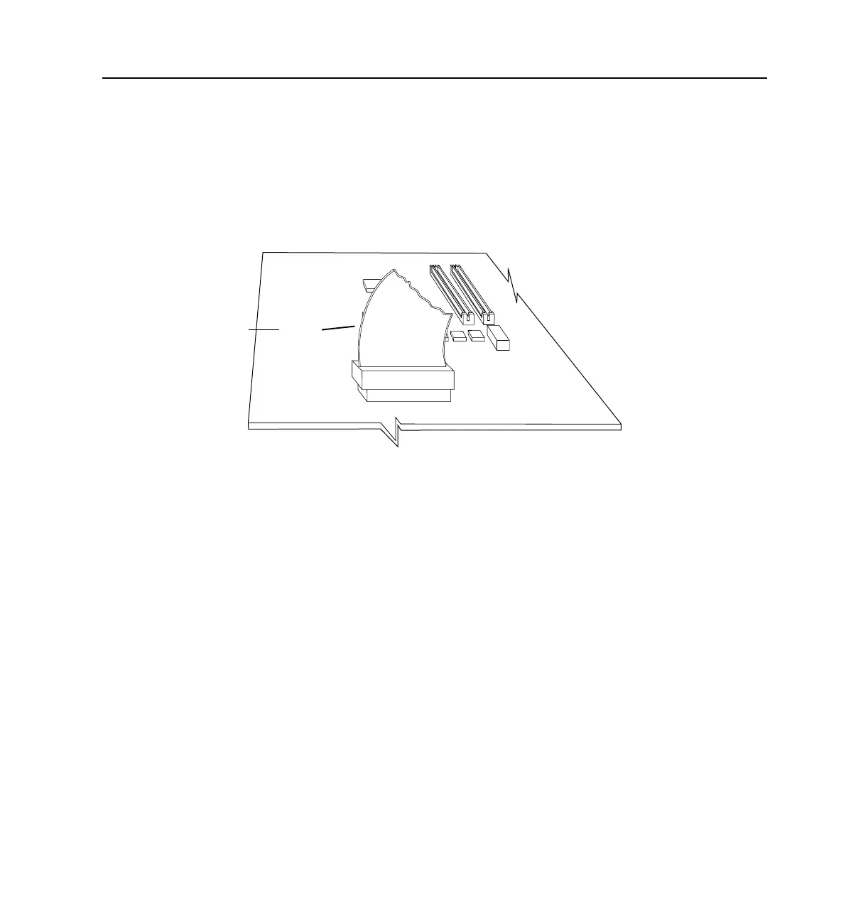
5. Ensure that a 60-pin ribbon has been installed in the center of the PortMaster
motherboard.
– If the ribbon is installed, proceed to Step 6.
– If the ribbon is not installed, insert the connector with the white strip on top
into the main board. Ensure that the red line is closest to the power supply
chamber.
6. If you are installing the MOD-101-U board, verify the board’s revision number.
The PortMaster 2ER requires revision C or later of the MOD-101-U board. Any
version of the MOD-101-U board can be used in the PortMaster 2E and
PortMaster 2Ei.
7. Verify the position of the expansion board jumper.
The jumper pin is located between the two cable connectors on the expansion
board.
– M0D-2E-10A and M0D-2E-10B asynchronous expansion boards. On these
boards, the jumper pins are marked 1 and 2.
For an S10 through S19 expansion board, verify that the jumper connects the
pair of pins marked 1 to the middle pair of pins.
1187_0025
red line
power supply
chamber