Installing PortMaster Expansion Boards
3-8 Communications Server Hardware Installation Guide
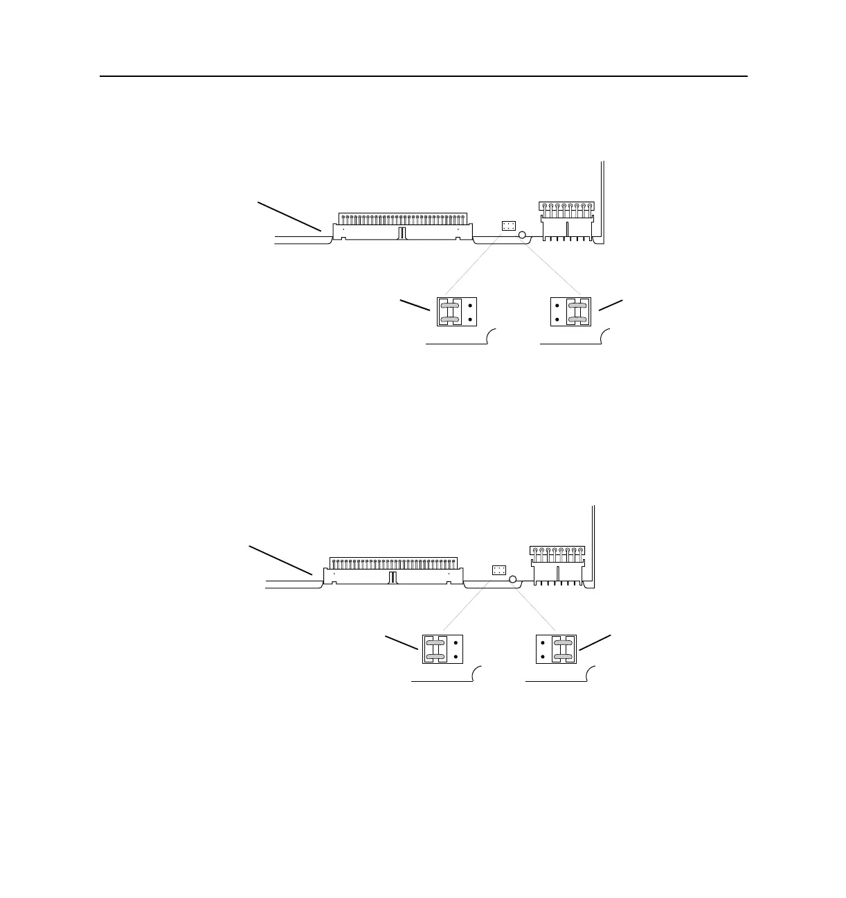
For an S20 through S29 expansion board, verify that the jumper connects the
pair of pins marked 2 to the middle pair of pins.
– MOD-10I-U and MOD-10I-ST ISDN. On these boards, the jumper pins are
marked 1, 2, and 3.
For an S10 though S19 expansion board, verify that the jumper connects the
pins 1 and 2.
For an S20 through S29 expansion board, verify that the jumper connects pins 2
and 3.
8. Using a Phillips screwdriver, remove the back cover plates from the rear of the
PortMaster.
– S10 through S19 expansion board. Insert this expansion board directly above
the rear face plate containing ports S0 through S9.
12
12 12
1187_0027
1187_0027
MOD-2E expansion board
for ports S10 though S19
for ports S20 though S29
12
1187_0028
3
12
3
12
3
1187_0028
for ports S20 though S29
for ports S10 though S19
MOD-10I expansion board