Installing Optional Equipment 3-9
Installing PortMaster Expansion Boards
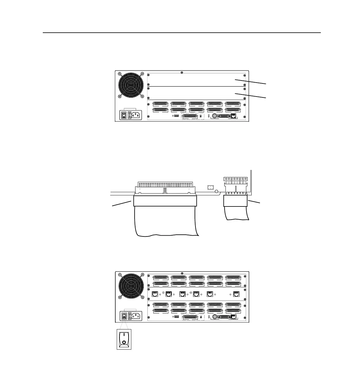
– S20 through S29 expansion board. Insert this expansion directly board above
the rear face plate containing ports S10 through S19.
9. Attach the rear face plates with the screws provided.
Ensure that each face plate is aligned before tightening the screws.
10. Plug the 8-wire ribbon power cable and 60-wire ribbon bus cable into the front
of each expansion board.
11. Replace the lid of the PortMaster case, and using a Phillips screwdriver, replace
the screw.
12. Connect the PortMaster to the power source and turn the power switch on.
S0
S5
S1
S6
S2
S7
RS-232
V.35
S3
S8
W1
S4
S9
ETHERNET
1187_0029
S10 through S19
S20 through S29
12
3
8-wire ribbon power cable
60-wire ribbon bus cable
1187-0037
S0
S5
S1
S6
S2
S7
RS-232
V.35
S3
S8
W1
S4
S9
ETHERNET
1187_0031
S20
S25
S21
S26
S22
S27
S23
S28
S24
S29
ISDN/U ISDN/U ISDN/U ISDN/U ISDN/U ISDN/U
S10-S11 S12-S13 S14-S15 S16-S17 S18-S19 HD
1187-0022
1187_0031