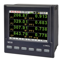
ND30PNET-09 - User's Manual
28
Selection of values at alarm and analog outputs Table 8
Value for percentage
calculations corresponding
to 100 % of the nominal
range.
current in outer conductor L1
reactive power of L1 phase
Un x In x sin(90°) [Var] *
apparent power of L1 phase
power factor PF of L1 phase
THD of L1 phase voltage**
current in outer conductor L2
reactive power of L2 phase
Un x In x sin(90°) [Var] *
apparent power of L2 phase
power factor PF of L2 phase
THD of L2 phase voltage**
current in outer conductor L3
reactive power of L3 phase
Un x In x sin(90°) [Var] *
apparent power of L3 phase
power factor PF of L3 phase
THD of L3 phase voltage**
average three-phase current
3-phase active power (P1+P2+P3)
3 x Un x In x cos(0°) [W] *
3-phase reactive power (Q1+Q2+Q3)
3 x Un x In x sin(90°) [Var] *
3-phase apparent power (S1+S2+S3)
phase-to-phase voltage L1-L2
phase-to-phase voltage L2-L3
phase-to-phase voltage L3-L1
phase-to-phase average voltage
averaged active power (P Demand)*
3 x Un x In x cos(0°) [W] *
averaged apparent power (S Demand)*
 Loading...