EasyManuals Logo

Lumel RE72 User Manual

Lumel RE72
96 pages
To Next Page IconTo Next Page
To Previous Page IconTo Previous Page
Page #8 background imageLoading...
Page #8 background image
8
8
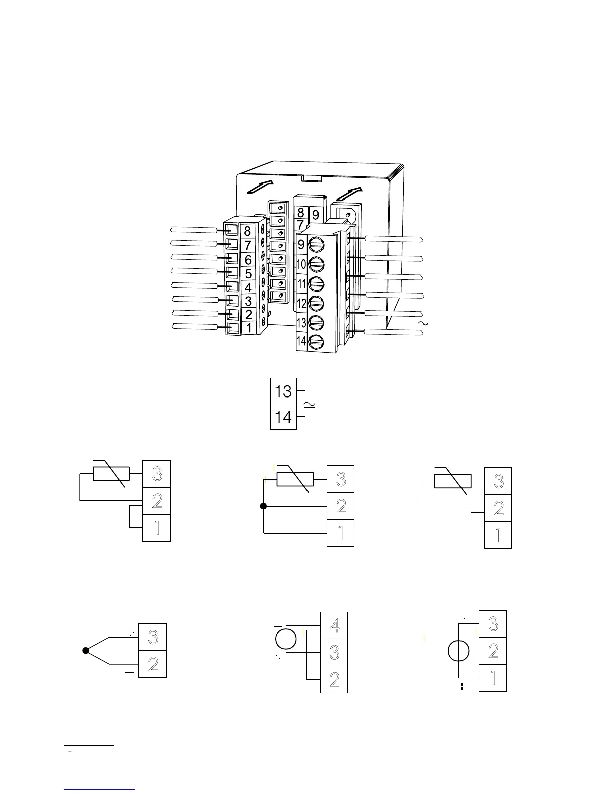
4.2. Electrical Connections
The controller has two separable terminal strips with screw termi-
nals. One strip enables to connect the supply and outputs by a wire
of 2.5 mm
2
cross-section. The second strip enables to connect input
signals by a wire of 1.5 mm
2
cross-section.
Fig. 3. View of controller connecting strips
supply
Fig. 4. Supply
3
2
1
Jumper
Pt100
zwora
3
4
2
+
-
0/4...20 mA
3
1
2
+
-
0...5/10 V
3
2
+
-
RTD Pt100 in two-wire
system
RTD Pt100 in 3-wire
system
Current input 0/4 ... 20 mA
Voltage input 0 ... 5/10 V
Thermocouple
RTD Pt1000
3
2
1
Pt100
3
2
1
zwora
Pt1000
3
2
1
zwora
Pt100
3
2
1
Pt100
3
2
1
Jumper
Pt1000
3
2
1
Jumper
Pt100
Jumper
3
4
2
+
-
0/4...20 mA
3
1
2
+
-
0...5/10 V
3
2
+
-
zwora
3
4
2
+
-
0/4...20 mA
3
1
2
+
-
0...5/10 V
3
2
+
-
Fig. 5. Input signals
interface RS-485
input 3/binary input/
transducer supply 24V
output 1
output 2
input signals
supply

Other manuals for Lumel RE72

Questions and Answers:

Question and Answer IconNeed help?

Do you have a question about the Lumel RE72 and is the answer not in the manual?

Lumel RE72 Specifications

General IconGeneral
BrandLumel
ModelRE72
CategoryController
LanguageEnglish