www.mabit.pl
info@mabit.pl
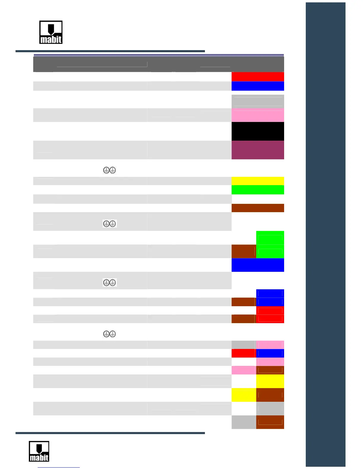
Clamp
no.
DESCRIPTION
RS232
Male
socket
RS232
Female
socket
Pin no. in
26PIN socket
Wire colors in SC5-
CAB-S and SC5-CAB-
D cables
1 Power supply +24VDC
1 RED
2 Power supply 0VDC ( -24VDC )
2 BLUE
3
Rx- signal reception for RS422 or four-wire
RS485 interface
3
GRAY
4
Rx+ signal reception for RS422 or four-wire
RS485 interface
4 PINK
5
Tx- signal transmission for RS422 or four-
wire RS485 interface or DATA- signal for
two-wire RS485 interface
5
BLACK
6
Tx+ signal transmission for RS422 or four-
wire RS485 interface or DATA+ signal for
two-wire RS485 interface
6 VIOLET
SHIELD
Wire shield, the clamp is connected to GND
clamps
11,12 wire SHIELD
7 GND for RS232 interface 5 5 7 YELLOW
8 RxD signal reception for RS422 interface
2 3
10
GREEN
7 GND for RS232 interface
5 5
8 WHITE
9 TxD signal transmission for RS422 interface 3 2 9 BROWN
SHIELD
Wire shield, the clamp is connected to GND
clamps
d-sub 9
socket
casing
d-sub 9
socket
casing
11,12 wire SHIELD
22
A signal ( 0-5V or 0-24V ) of hand wheel (
GND – pin no. 2 )
14 WHITE 22
23
B signal ( 0-5V or 0-24V ) of hand wheel (
GND – pin no. 2 )
13 BROWN 23
2
GND for A and B signals is 0VDC of the
power supply
2 BLUE
SHIELD
Wire shield, the clamp is connected to GND
clamps
11,12 wire SHIELD
18 /A signal RS422 of hand wheel 16 WHITE 18
19 A signal RS422 of hand wheel 15 BROWN 19
20 /B signal RS422 of hand wheel 18 WHITE 20
21 B signal RS422 of hand wheel 17 BROWN 21
SHIELD
Wire shield, the clamp is connected to GND
clamps
11,12 wire SHIELD
10 NO contact no. 1 of Approval key 20 GRAY 10
11 NO contact no. 1 of Approval key 22 RED 11
12 NO contact no. 2 of Approval key 24 WHITE 12
13 NO contact no. 2 of Approval key 26 PINK 13
14
NC contact no. 1 of Emergency off switch/
Emergency stop
25 WHITE 14
15
NC contact no. 1 of Emergency off switch/
Emergency stop
23 YELLOW 15
16
NC contact no. 2 of Emergency off switch/
Emergency stop
21 WHITE 16
17
NC contact no. 2 of Emergency off switch/
Emergency stop
19 GRAY 17