INSTALLATION INSTRUCTIONS
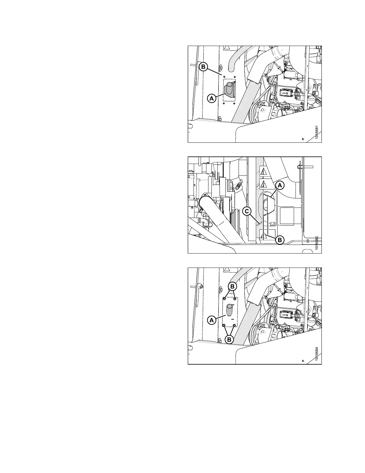
5. With bolts and plate removed, slide aspirator
assembly (A) out of fan shroud (B).
6. Install the new aspirator assembly.
Figure 3.3: Aspirator Assembly
7. Adjust new
aspirator assembly (A) within th e s h r oud
to achieve
minimum 13/32 in. (10 mm) clearance (B)
between th
e aspirator (A) and the engine cooling
fan (C).
Figure 3.4: Aspirator Clearance
8. Reinst
all the plate (A) and the four bolts (B) that were
remov
ed in Step 4, page 9. Torque bolts to 18–20 ft·lbf
(24–2
7N·m).
Figure 3.5: Aspirator Assembly
167730 10 Revision B