INSTALLATION INSTRUCTIONS
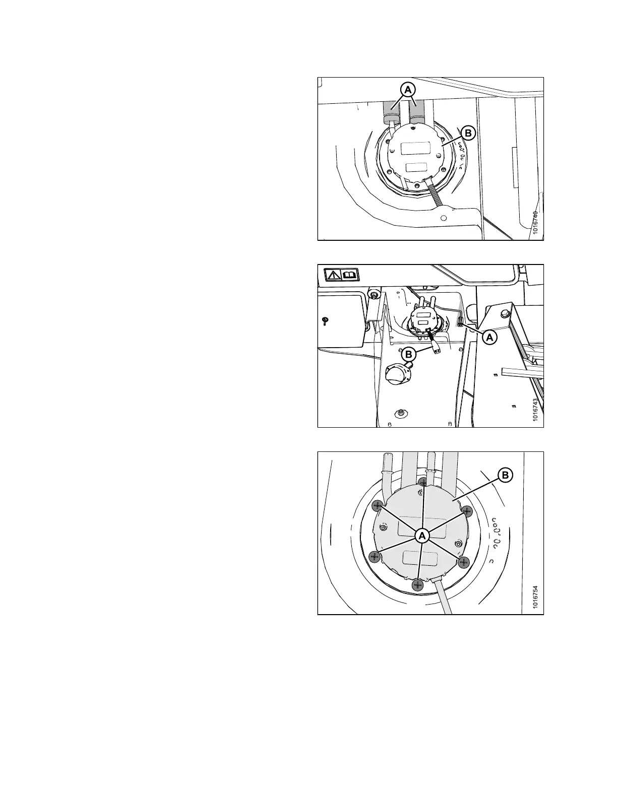
17. Mark the position of the two black corrugated DEF
lines (A) attached to the DEF head (B).
NOTE:
Connection points are identical on the new
DEF head.
18. Press the black strip on the side of the quick-connect
fitting (A), and disconnect fitting fro m pilot on DEF
head (B).
Figure 3.31: Hoses on DEF Head
19. Disconnect the wiring harness (A) going to the DEF
head (B). Cover the exposed connectors on the
harness with tape to protect from spills.
NOTE:
Part o f tank made tra nsparent in illustration
to show where the harness connects on the
DEF head.
Figure 3.32: Harness on DEF Head
20. Usin g a Phillips screwd river, remove the six pan head
screws (A) holding the DEF head (B) to the tank.
Retain screws for use later.
Figure 3.33: DEF Head
167730
22
Revision B