INSTALLATION INSTRUCTIONS
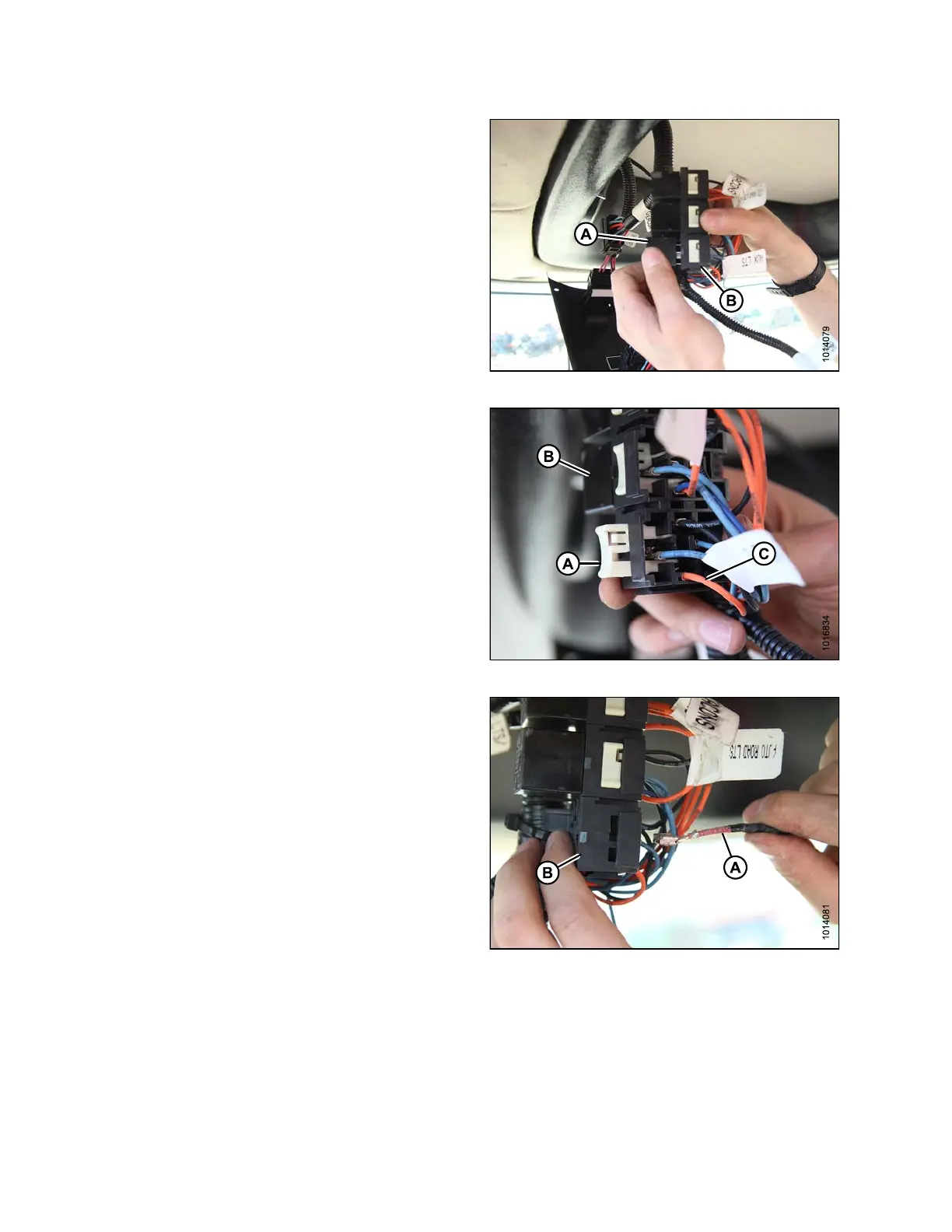
5. Remove the auxiliary lights relay (A) from its s oc ke t (B).
Figure 3.46: Auxiliary Lights Relay and S ocket
6. Remove the terminal lock (A) from th e relay so cket (B).
7. Remove the existing AUXILIARY LTS (orange) wire (C)
from port 30 of the relay socket (B) with a wire extractor
tool such as Delphi pin removal tool MD #134159 or
equivalent.
8. Seal the AUXILIARY LTS (orange) wire (C) with heat
shrink material included in kit MD #167693.
Figure 3.47: Auxiliary Lights Relay
9. Remove t he A UXILIARY LT S (red) wire (A) from
port 87a and connect it to port 30 on the relay
socket (B).
Figure 3.48: Wires and Relay Socket
167730 28 Revision B