Mackie TT24 Digital Live Console Quickstart Guide TT24 Interface
12
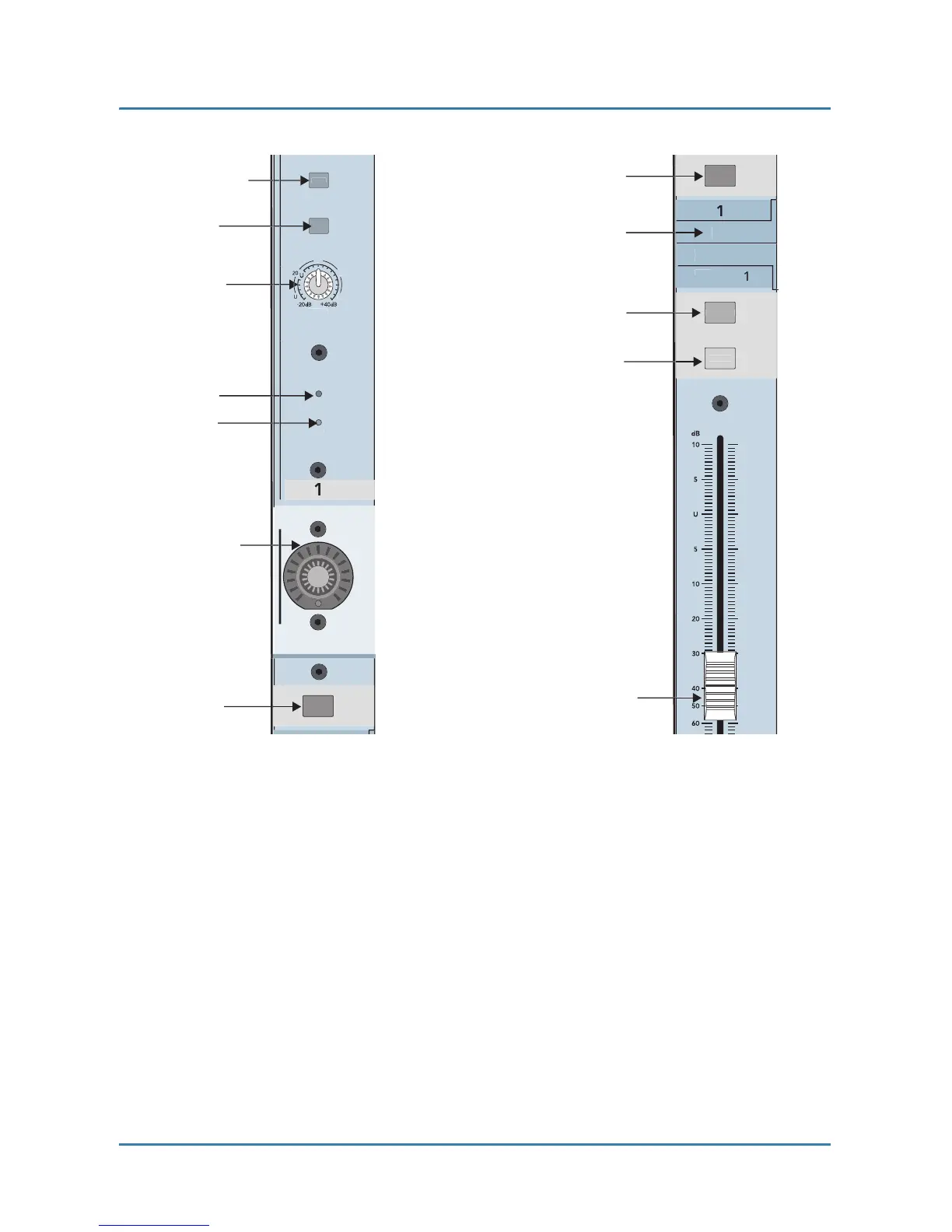
Figure 2-1 Channel strip
:
top (left), bottom (right)
2.2 Banks
The four Bank select buttons on the TT24 change the function of the 24 channel
strips to control the following groups of channels (Figure 2-2)
:
ANALOG
:
24 analog mic/line inputs
DIGITAL
:
There are 24 digital inputs from three ADAT optical connectors on
the rear panel (44.1/48 kHz). At 96 kHz, there are 12 digital inputs from the
three built
-
in connectors
;
another 12 are available from the optional ADAT I/O
expansion card.