13
Owner’s Manual
Owner’s Manual
3.1.6 MUTE
Push the MUTE button to toggle the channel between
muted (button lights) and enabled (not lit).
NOTE: Pre-fader Aux sends can be globally
changed to pre- or post-mute from the
SETUP-GENERAL Touchscreen (see page 46).
3.1.7 Bank/Channel Description Area
This area indicates the audio signal currently con-
trolled by the channel strip. Each channel strip can con-
trol one channel from one of the four banks at any given
time. For example, Figure 3-1 illustrates channel strip
1. Four channel names are listed in the Bank/Channel
Description Area:
• If the ANALOG bank is selected, strip 1 controls
analog Channel 1.
• If the DIGITAL bank is selected, strip 1 controls
digital Channel 25.
• If the RETURNS bank is selected, strip 1 controls
Line Input 1.
• If the MASTERS bank is selected, strip 1 controls
Aux Send 1.
3.1.8 SELECT
When lit, the SELECT button indicates this channel
is selected for:
• display and control of its parameters on the Touch-
screen.
• assignment to groups in conjunction with the
GROUP ASSIGN/SELECT controls (see Group and
Master Controls on page 19).
Channel Linking
Pressing and holding the SELECT buttons on an
odd/even pair of adjacent channels for two seconds
links their functions. A Touchscreen window requests
confirmation: “Link Channel X and Y?” Touch YES to
link the channels or CANCEL to abort the process. To
unlink channels, press and hold both SELECT buttons
for two seconds again. A Touchscreen window requests
confirmation: “Unlink Channel X and Y?” Touch YES to
unlink them or CANCEL to leave them linked.
After linking, the odd channel’s settings are copied to
the even channel; adjusting a setting on either channel
duplicates the setting on the other. The only exception
to this rule is panning. The pans are inversely related
between linked channels: Panning one channel fully left
pans the other fully right; panning one channel to 10:00
pans the other to 2:00.
True stereo compression applies to linked channels so
the summed signal is delivered to the stereo compressor.
3.1.9 SOLO
Press the SOLO button to solo the channel. This yel-
low backlit button lights when the channel is soloed.
The PFL/AFL global selection is done in the Solo master
section (see Solo Area on page 19).
The default Solo behavior is to allow multiple soloed
channels. However, enable EXCLUSIVE SOLO mode (in
the SETUP-GENERAL Touchscreen) to have each Solo
selection deactivate the previous one. In EXCLUSIVE
SOLO mode, pressing CTRL+SOLO solos additional
channels.
3.1.10 Channel Fader
The motorized 100mm fader controls the channel
level. Its function depends on the selected Bank (see
Bank Select Area below).
In Aux Mode (page 15), the fader controls the level
of the channel Aux sends 1–12 and depends on the Aux
selection in the V-POT CONTROL area (see page 14). It
is variable from -∞ to +10 dB in logarithmically scaled
steps.
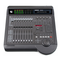
3.2 Bank Select Area
The four Bank Select buttons (ANLG, DGTL, RTNS,
MSTR) change the mapping to the 24 channel strips
(Figure 3-3). The four buttons intercancel and one is
always active. All channels retain their settings between
Bank changes.
3.2.1 ANALOG
Press the ANLG but-
ton to select the ANALOG
bank. The button lights red
and the 24 analog mic/line
inputs are assigned to chan-
nel strips 1–24.
3.2.2 DIGITAL
Press the DGTL button to
select the DIGITAL bank.
The button lights green and
the DIGITAL inputs are as-
signed to the channel strips
1–24.
At 44.1/48 kHz, there are 24 digital inputs from three
ADAT optical connectors on the rear panel. At 96 kHz,
there are 12 digital inputs from the three built-in ADAT
optical connectors.