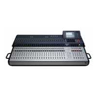
Ch 2: Quickstart Tutorial
3. Set the LINE switch to the up (mic) position.
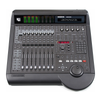
Mute button
4.
Set the 48V switch to the down position if the mic uses
phantom power; set it to the up position otherwise.
Set the channel gain
5. Activate the PFL button (right of Figure 2-2).
6. Activate channel 1’s SOLO button (above fader) to
solo the channel.
7. Provide a representative signal to the mic, watch
the meters to the right of the Touchscreen, and
listen in phones (the phones level is in the UTILITY
area).
The solo level should be between -7 and -10 dBFS.
8. Press channel 1’s SOLO button again or CLEAR
SOLO (left of PFL) to unsolo.
Route channel 1 to Main output, Group 1, and Aux 1
9. Press and hold the L/R button in the GROUP AS-
SIGN area (Figure 2-3) and activate channel 1’s
SELECT button.
All the channel SELECT buttons light, indicating
that all channels are routed to the Main output. You
should hear your mic in the speakers connected to
MAINS OUT via the master fader.
Let’s route the mic through Group 1 instead of directly
to MAINS OUT:
10. Press and hold the L/R button in the GROUP AS-
SIGN area and deactivate channel 1’s SELECT
button (so it is not lit).
Channel 1 no longer sends signal to MAINS OUT.
11. Press and hold the Group 1 button in the GROUP
ASSIGN area and activate channel 1’s SELECT button.
The mic is now routed to Group 1.
12. Press and hold the L/R button in the GROUP AS-
SIGN area and activate Group 1’s SELECT button.
Group 1 is now assigned to LEFT and RIGHT
MAINS OUT.
Use the channel, Group, and Master fader to listen
to the mic signal in the speakers connected to
MAINS OUT.
Figure 2-2 Top of channel strip (left); Bank select, Clear
Solo, PFL, V-Pot control (right)
This Quickstart Tutorial will help you begin using
the TT24 quickly and easily by providing step-by-step
instructions for its most commonly utilized tasks. Rest
assured that our team of design engineers has verified
these instructions! It may be helpful to refer to Appen-
dix B: Configurations and Block Diagrams to see how
several useful complete systems are interconnected.
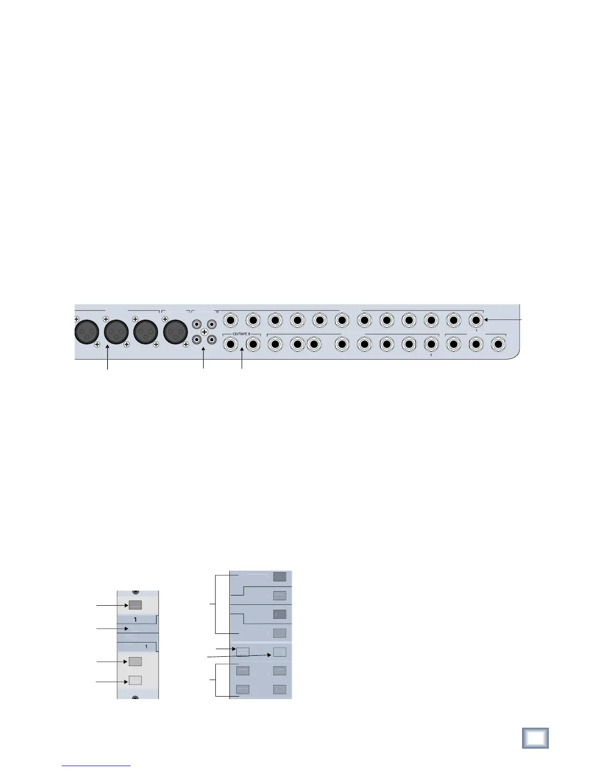
2.1 Connect Amplifier/Speakers
1. Plug in a pair of amps/speakers into the MAINS OUT
LEFT and RIGHT XLR connectors (Figure 2-1).
2. Connect an amp/speaker to AUX SEND 1.
3. Plug in headphones.
Figure 2-1 Mains and Aux Sends Outputs
2.2 Connect a Mic
This section describes how to connect a mic to chan-
nel 1, set the gain, route to groups/auxes, and engage/
adjust the variable high-pass filter.
Connect mic to channel 1
1. Plug a mic into channel 1’s XLR input (top-right of
rear panel).
2. Press the ANLG bank select button (right of
Figure 2-2).