14
TT24 DIGITAL LIVE CONSOLE
TT24 DIGITAL LIVE CONSOLE
3.2.3 RETURNS
Press the RTRN button to select the RETURNS bank.
The button lights red and the following inputs are con-
trolled on the channel strips:
1–8: Eight analog line inputs (TRS connectors on rear
panel) 9–16: Four internal stereo effects returns 17–24:
Return channels from expansion cards
3.2.4 MASTER
Press the MSTR button to select the MASTERS bank.
The button lights green and the following inputs are
controlled on the channel strips:
1–12: Twelve Aux send masters 13–20: Eight Group
masters 22–24: Left, Right, and Center/Mono Main
outputs
NOTE: The Left and Right faders are always linked. The Left-Right
and Center/Mono faders may be linked as needed.
3.2.5 USER BANK
A customizable user bank allows you to compile a
new bank of 24 faders containing any of the channels
included in the 4 primary banks (ANLG, DGTL, RTNS,
MSTR).
To access the user bank for mixing simply press the
ANLG and DGTL bank select buttons simultaneously.
They will both illuminate and the faders will snap to
their current settings, indicating the
TT24 is in the user bank. See section
6.13.5 for more information on config-
uring the user bank.
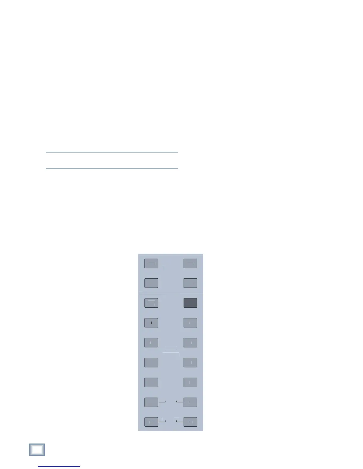
3.3 V-Pot Control
Area
The buttons to the right of the
channel faders assign the current
function to the channel V-Pots. These
include the four V-POT CONTROL
buttons (PAN, TRIM, METERS,
HPF), AUX SENDS 1–12, and AUX
PAN (see Figure 3-4). These buttons
all intercancel so only one can be ac-
tive at a time.
AUX PAN operates for stereo-
linked Aux sends only, and does not
deselect the selected Aux send but-
ton. When selected, a single LED illu-
minates around the V-Pot to indicate
the pan position.
The AUX MODE button is discussed in this section
because of its relevance to the other Aux buttons. How-
ever, it does not intercancel with the other buttons.
3.3.1 TRIM
Digital Trim, available only to the ANALOG bank, is
used to adjust the input level just after the ADC, and
channel meter, and before the channel DSP. This allows
setting the analog gain for the optimal A/D conversion
while still having an adjustable input level to the chan-
nel DSP. This also provides a method to lower the level
of all channel outputs and sends at once: Digital Trim is
before the Aux and Group sends in the signal flow.
The Digital Trim provides ±15 dB of attenuation or
gain, adjustable in 0.1 dB increments and is indicated by
a single, lit LED. When the Digital Trim is set to unity,
the top LED (12:00 position) and the bottom V-Pot LED
illuminate.
3.3.2 PAN
Pan position is indicated by a single, lit LED. When
the pan is exactly centered, the top LED (12:00 posi-
tion) and the bottom V-Pot LED illuminate.
LR or LCR panning is available on the ANALOG, DIGI-
TAL, and RETURNS banks and the eight groups (mode
dependent) of the MASTER bank.
3.3.3 HPF
The high-pass filter can remove unwanted
low frequencies from an input channel. The
filter cutoff frequency range is 20–400 Hz; the
default frequency is 80 Hz. The HPF has a
fixed slope of 18 dB/octave. The approximate
frequency is indicated by a single lit V-Pot
LED (frequency increases clockwise). Push
the V-Pot to toggle the HPF on/off; the bottom
red LED lights when the HPF is on. Press
the SELECT button on an individual chan-
nel, then press the EQ Quick-Mix button to
see the HPF frequency range as you turn the
V-Pot.
3.3.4 METERS
The V-Pot LEDs serve as a meter (indicat-
ing left to right) for the channel’s signal level.
The bottom, red LED illuminates to indicate
digital clipping (0 dBFS).
Push the V-Pot knob to toggle the meter
to show compressor reduction: the LEDs
now illuminate counterclockwise (the knob
controls the compressor threshold setting).
The bottom, red LED lights continuously to
indicate the compressor reduction mode of
the meter. This can be activated individually
Figure 3-4 V-Pot Control Area