Version 1.6
50 | Installation
MG6250 • Section Programming Guide
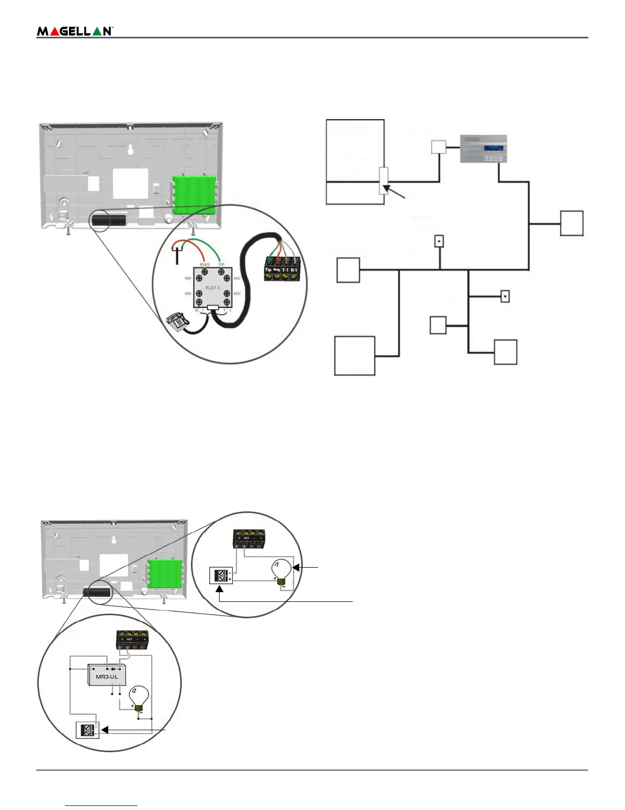
Telephone Line Connections
The MG6250 console can be connected to a telephone line by connecting the telephone company’s wires directly to the dialer of the console.
Direct Connect
Connect the telephone line through a RJ31X jack as shown in figure 11.
Figure 11: Telephone Line Direct Connect
Programmable Outputs (PGMs)
The MG6250 comes equipped with two 50mA open-collector outputs; Max. handling current 50mA. When a specific event occurs in the system, a PGM can be
programmed to activate lights, garage door openers, etc. See PGM Options on page 10 for more information on programming PGMs.
Connect the MG6250 PGM outputs as shown in Method 1 in figure 12. Since the MG6250 does not come with a power supply, an external power supply must be
employed to power the circuit.
If the current draw on the PGMs is to exceed 50mA, we recommend using an external relay as shown in Method 2 in figure 12. For connecting the PGM2, see figure
13.
NOTE: Using Method 2, connect the device to the output terminal of the external relay that matches the normal state of the MG6250’s PGM output. Keep in mind
that the maximum voltage of PGM1 and PGM2 is 12Vdc.
Figure 12: PGM1 and PGM2 Connections
To connect the
telephone line:
1. Connect a RJ31X to
the R-1, T-1, RING
and TIP terminals as
shown above.
2. Connect the telephone
company wires and the home
telephone on the RJ31X.
Telephone
Computer
Telephone
Telephon e
Magellan
demarcation point
Network
Unused
RJ-11 jack
Answering
machine
Unused
RJ-11 jack
console
RJ31X
or
RJ38X
jack
Service
Network
Provider’s
Facilities
Telephone line
Method 1
(less than 50mA)
Method 2
(more than 50mA)
External DC Power Supply
Devices such as light, etc.
Devices such as light, etc.
External relay
BLK
RED
COM
(WHT)
YEL
N.C. N.O.
GRN