3 Electrical Installation
8 MAGNETEK HPV1000 AC Elevator Drive Technical Manual
Control Circuit Output Terminal Functions
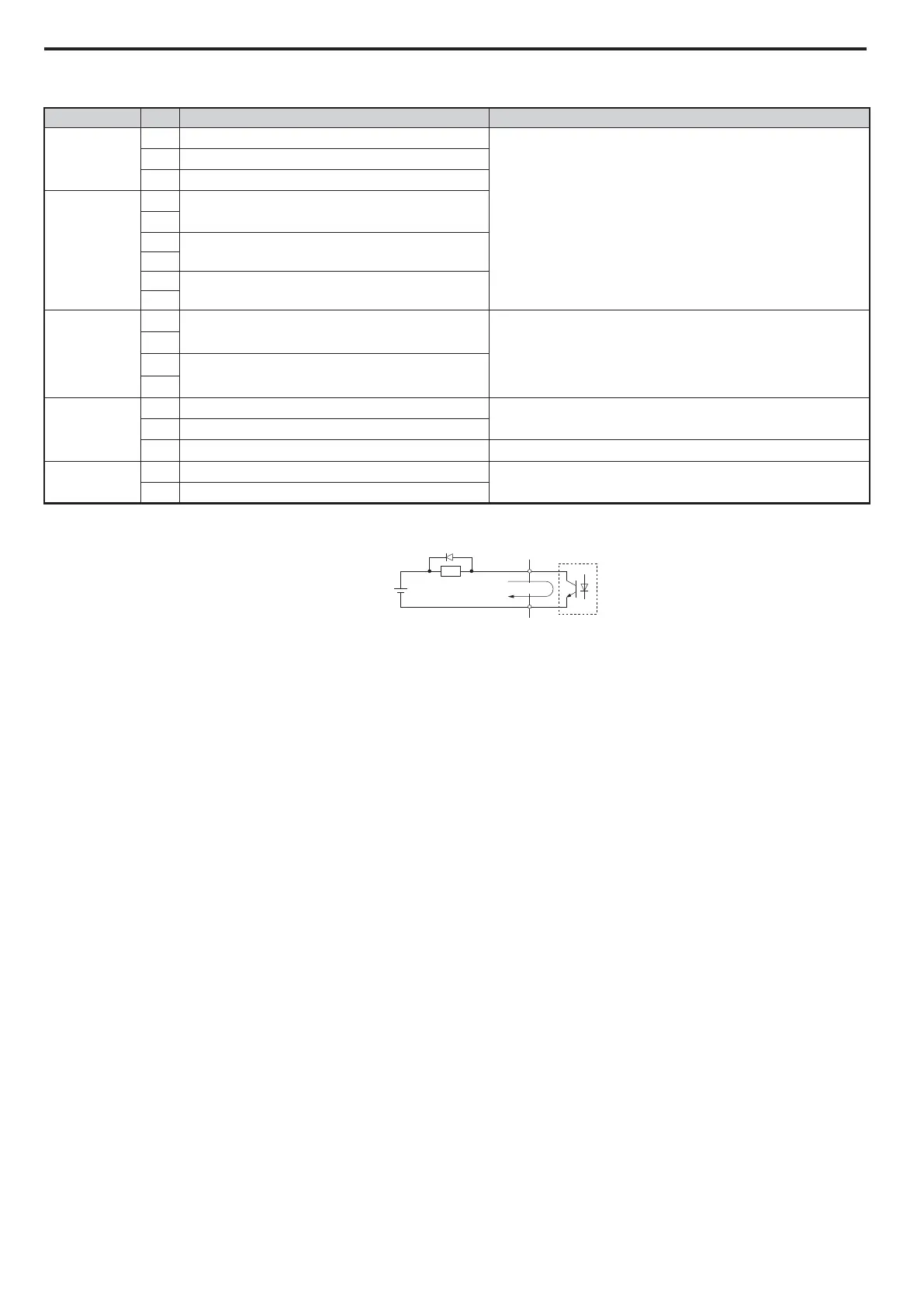
NOTICE: When connecting a reactive load such as a relay coil to a photo coupler output, attach a flywheel diode to the load (relay coil)
like shown below. Ensure the diode rating is greater than the circuit voltage.
Encoder Terminations
When the HPV1000 is used with an encoder the following points should be noted:
• Use twisted pair cable with shield terminated at drive end only.
• Encoder wiring should be routed at least 30cm from motor cable or power.
• Continuity of wires and shields should be maintained from the encoder through to the controller, avoiding the use of
terminals in a junction box.
• The shield and shield drain wires must be insulated from other objects. This helps to minimize radiated and induced
noise problems and magnetically induced ground loops.
• Use direct motor mounting without couplings where possible.
• Should the encoder to be connected to the motor via a coupling, the encoder should not oscillate when the motor is
turning, as this will result in a compromised ride quality and possibly drive faults occurring.
• When attempting to configure a drive for closed loop/PM operation an option card is required, when a standard
Incremental encoder is used the PG-X3 option card is required, for EnDat encoders the PG-F3 card is required.
For the correct termination information please refer to Closed-Loop Startup on page 34 and PM Startup on page 37.
Type No. Terminal Name Function (Signal Level) Default Setting
Fault Relay
MA
N.O. output
30 Vdc, 10 mA to 1 A; 250 Vac, 10 mA to 1 A
Minimum load: 5 Vdc, 10 mA
MB
N.C. output
MC
Fault output common
Multi-Function
Relay Output
M1
Multi-function Relay output 1
M2
M3
Multi-function Relay output 2
M4
M5
Relay output 3
M6
Multi-Function
Photocoupler
Output
P1
Photocoupler output 1
Photocoupler output 48 Vdc, 2 to 50 mA
C1
P2
Photocoupler output 2
C2
Monitor Output
FM
Analog monitor output 1
-10 to +10 Vdc, 0 to +10 Vdc
AM
Analog monitor output 2
AC
Monitor common 0 V
Safety Monitor
Output
DM+
Safety monitor output
Outputs status of Safe Disable function. Closed when both Safe
Disable channels are closed. Up to +48 Vdc 50 mA.
DM–
Safety monitor output common
DC Power
Supply (max 48 V)
Flywheel diode
Reactive
load
I (max 50 mA)