5 Programming
MAGNETEK HPV1000 AC Elevator Drive Technical Manual 29
Display Menu Parameters
Table 15 ELEVATOR DATA D1 Submenu
D1 Parameter Name Description
Units
Speed Command
Speed Command:
Displays the commanded speed from the controller.
m/s
Speed Reference
Speed Reference:
Displays the drive speed reference.
m/s
Speed Feedback
<2>, <3>, <4>
Speed Feedback:
Displays the speed feedback measured from the motor.
%
<3>, <4>
Speed Error <3>, <4>
Speed Reference-Speed Feedback:
Shows the amount of speed error seen by the encoder.
m/s
<2>, <3>, <4>
Encoder Speed
Encoder Speed:
Displays the measured speed from the encoder.
RPM
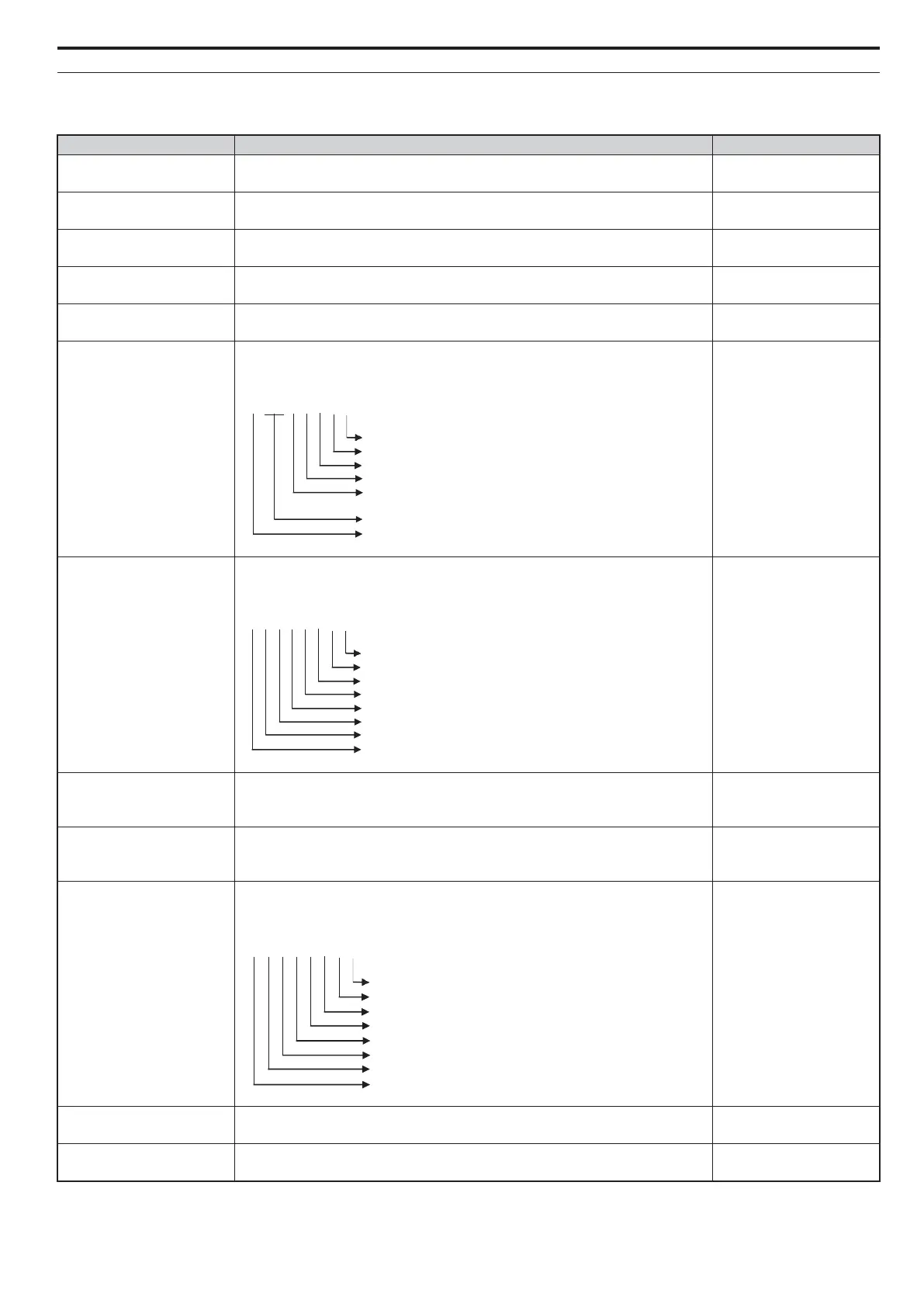
Logic Outputs
Output Terminal Status:
Displays the output terminal status.
1 = on, 0 = off
Logic Inputs
Input Terminal Status:
Displays the input terminal status.
1 = on, 0 = off
SrlBytesReceived
Serial Bytes Received:
Number of valid HPV Mode 1 Runtime bytes the drive received after a power up.
Note: The value rolls over after 65535.
number of byte
SerialBytesSent
Serial Bytes Received:
Number of valid HPV Mode 1 response bytes the drive received after a power up.
Note: The value rolls over after 65535.
number of byte
Drive Status
Internal Control Status:
Displays the input terminal status.
1 = on; 0 = off
Analog A1 Level
Terminal A1 Level:
Displays the voltage input to terminal A1.
%
Analog A2 Level
Terminal A2 Level:
Displays the voltage input to terminal A2.
%
00000000
Terminal M1-M2
Terminal M3-M4
Terminal M5-M6
Terminal P1-C1
Terminal P2-C2
N/A
Terminal MA-MB-MC
00000000
Terminal S1
Terminal S2
Terminal S3
Terminal S4
Terminal S5
Terminal S6
Terminal S7
Terminal S8
00000000
During run
During zero-speed
During down direction
During fault reset signal input
During speed agree
During ready
During alarm detection
During fault detect