8 Appendix
MAGNETEK HPV1000 AC Elevator Drive Technical Manual 69
Low Voltage Wiring for Control Circuit Terminals
Wire low voltage wires with NEC Class 1 circuit conductors. Refer to national state or local codes for wiring. If external
power supply used, it shall be UL Listed Class 2 power source only or equivalent. Refer to NEC Article 725 Class 1,
Class 2, and Class 3 Remote-Control, Signaling, and Power Limited Circuits for requirements concerning class 1 circuit
conductors and class 2 power supplies.
Drive Short-Circuit Rating
This drive is suitable for use on a circuit capable of delivering not more than 100,000 RMS symmetrical amperes, 600
Vac maximum (up to 480 V for 400 V class drives) when protected by Bussmann Type FWH.
EMC Guidelines Compliance
This drive is tested according to European standards IEC/EN 61800-3: 2004, and complies with the European standards
IEC/EN 12015 (requires an optional AC reactor) and IEC/EN 12016.
Note: Make sure the protective earthing conductor complies with technical standards and local safety regulations. Because the leakage
current exceeds 3.5 mA when an EMC filter is installed, IEC/EN 61800-5-1 states that either the power supply must be
automatically disconnected in case of discontinuity of the protective earthing conductor or a protective earthing conductor with a
cross-section of at least 10 mm
2
(Cu) or 16 mm
2
(Al) must be used.
EMC Filter Installation
The following conditions must be met to ensure continued compliance with European standards IEC/EN 12015 and IEC/
EN 12016. Refer to EMC Filters, Fuses and Dynamic Braking Resistors on page 71 for EMC filter selection.
Installation Method
Verify the following installation conditions to ensure that other devices and machinery used in combination with this
drive also comply with EMC guidelines.
1.
Install an EMC noise filter to the input side specified by Magnetek for compliance with European standards.
2. Place the drive and EMC noise filter in the same enclosure.
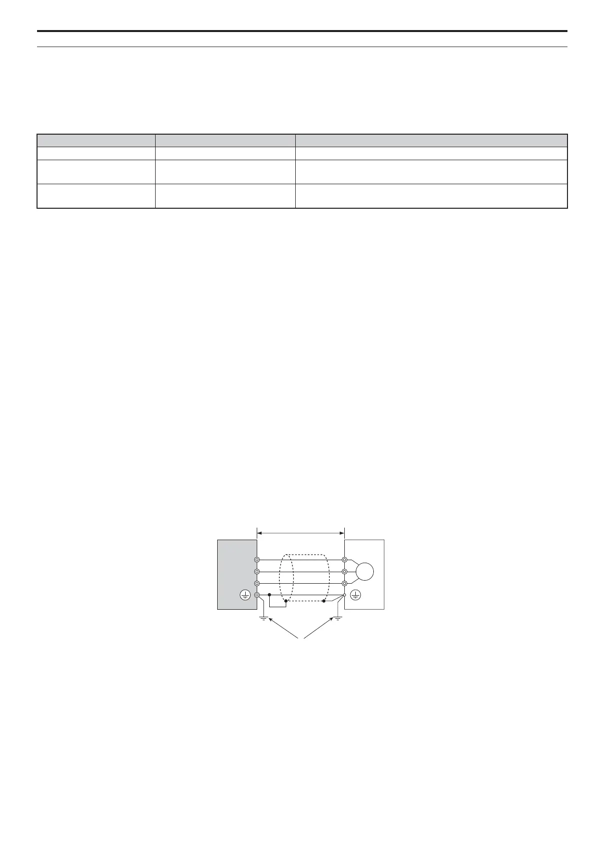
3. Use braided shield cable for the drive and motor wiring, or run the wiring through a metal conduit.
4. Keep wiring as short as possible. Ground the shield on both the drive side and the motor side.
Figure 8
Figure 11 Installation Method
5. Make sure the ground conductor complies with technical standards and local safety rules. When an EMC filter is
installed, the leakage current exceeds 3.5 mA. Therefore according to IEC/EN 61800-5-1, at least one of the
conditions below must be satisfied:
a. The cross-section of the protective earthing conductor must be at least 10 mm
2
(Cu) or 16 mm
2
(Al).
b. The power supply must be disconnected automatically in case of discontinuity of the protective earthing
conductor.
Input / Output Terminal Signal Power Supply Specifications
Open Collector Outputs P1, C1, P2, C2, DM+, DM- Requires class 2 power supply.
Digital inputs S1-S8, SN, SC, SP, HC, H1, H2
Use the internal LVLC power supply of the drive. Use class 2 for external
power supply.
Analog inputs / outputs +V, -V, A1, A2, AC, AM, FM
Use the internal LVLC power supply of the drive. Use class 2 for external
power supply.
A – Drive D – Metal conduit
B – 10 m max cable length between drive and motor E – Ground wire should be as short as possible.
C – Motor