4 MAGNETEK HPV1000 AC Elevator Drive Technical Manual
3 Electrical Installation
3 Electrical Installation
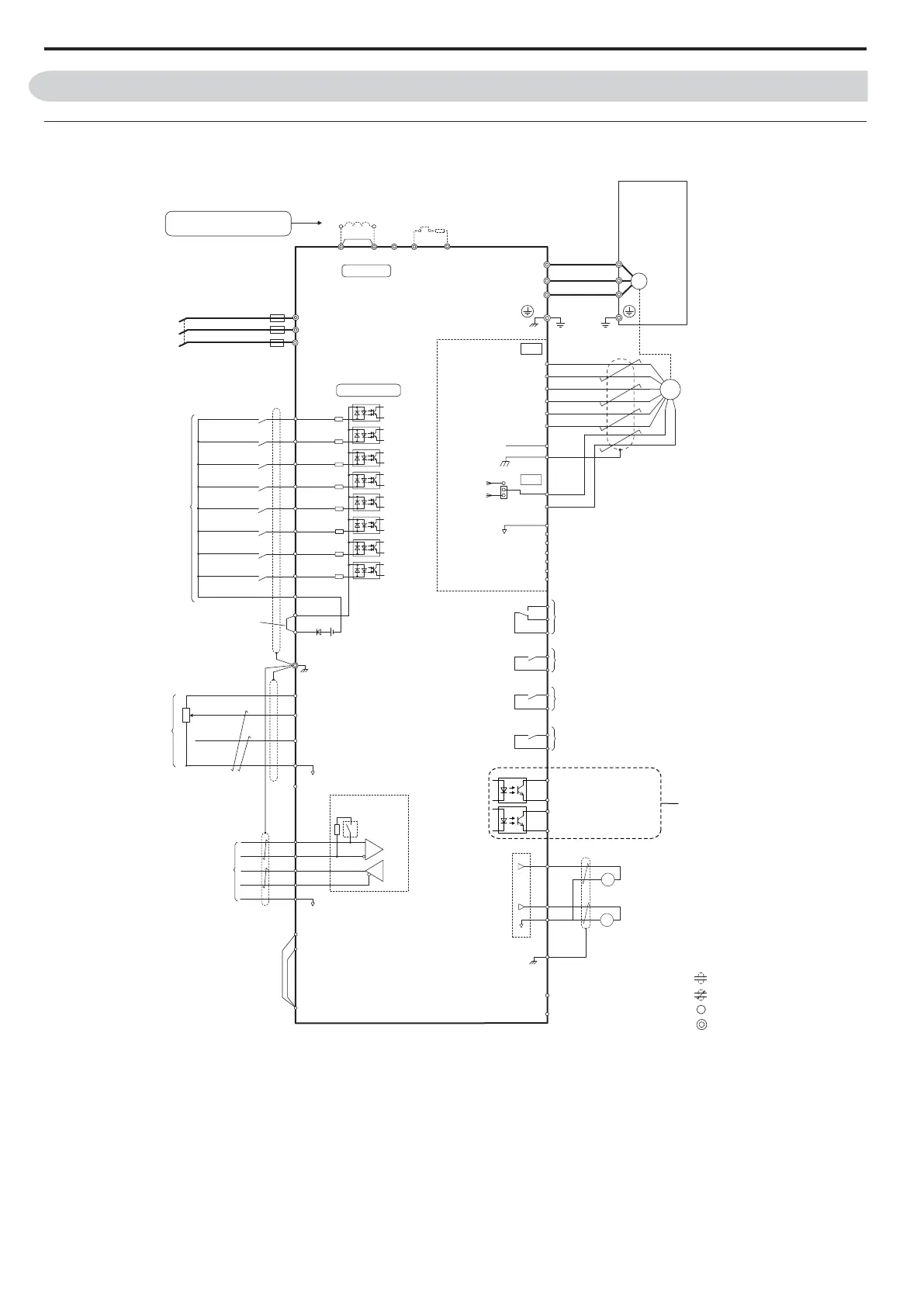
Electrical Interconnections
Note: 1. The drive should be implemented in the system in a way so that a drive fault causes the safety chain to open. Always use terminal
MA-MB-MC for this purpose.
<1> Remove the jumper when installing a DC reactor. Models 4045 up to 4216 come with a built-in DC reactor.
<2> Never short terminals SP and SN, as doing so will damage the drive.
<3> Disconnect the wire jumper between H1-HC and H2-HC when utilizing the Safe Disable inputs.
Shield ground terminal
++
DM
DM
H
1
H2
HC
R/L1
S/L2
T/L3
Fuse
P1
P2
C1
C2
Photo Coupler 1
Photo Coupler 2
Digital output
5 to 48 Vdc
2 to 50 mA
(default setting)
+
+
++
Never connect power supply lines
to the B2, +1, +2, B1 terminals
DC link choke
(option)
UX
Thermal relay
(option)
+
+
++
+
UX
S
1
S2
S3
S4
S5
S6
S7
A1
A2
0
V
AC
R
R
S
S
IG
HPV1000
Drive
B112
B2
2
kΩ
S8
SC
0 V
FM
AM
AC
E (G)
<1>
+
24 V
+V
MA
M
1
M2
MB
MC
Jumper
Braking resistor
(option)
Logic Input 1
Logic Input 3
Logic Input 4
Logic Input 5
Logic Input 8
Multi-function
digital inputs
Sink / Source mode
selection wire jumper
(default: Sink)
Multi-function
analog inputs
Power supply +10.5 Vdc, max. 20 mA
Analog Input 1
-10 to +10 Vdc (20 k
Ω
)
Analog Input 2
-10 to +10 Vdc (20 k
Ω
)
−V
Power supply, -10.5 Vdc, max. 20 mA
comm. RS485/422
max. 115.2 kBps
Termination resistor
(120
Ω
, 1/2 W)
DIP
Switch S2
Fault
250 Vac, max. 1 A
30 Vdc, max 1 A
(min. 5 Vdc, 10 mA)
Multi-function relay output
250 Vac, max. 1 A
30 Vdc, max 1 A
(min. 5 Vdc, 10 mA)
Multi-function analog output 1
-10 to +10 Vdc (2mA)
Multi-function analog output 2
-10 to +10 Vdc (2mA)
Main Circuit
Control Circuit
shielded line
twisted-pair shielded line
main circuit terminal
control circuit terminal
M3
M4
Multi-function relay output
250 Vac, max. 1 A
30 Vdc, max 1 A
(min. 5 Vdc, 10 mA)
M5
M6
Multi-function relay output
250 Vac, max. 1 A
30 Vdc, max 1 A
(min. 5 Vdc, 10 mA)
SP
SN
FM
+
AM
Logic Input 2
Logic Input 6
Logic Input 7
M
U/T
1
V/T2
W/T
U/T1
V/T2
W/T3
3
Ground
EDM (Safety Electronic Device Monitor)
Safe Disable inputs
PG-X3
Option
Encoder
–
–
–
<2>
<3>
–
Figure 3
TB1
TB2
A
+
A–
B+
B–
Z+
Z–
a+
a–
b+
b–
z+
z–
IP
IG
SD
FE
SG
A Channel
A-Channel
B Channel
B-Channel
Z Channel
(if present)
Z-Channel (if present)
NC
CN3
12V
5V
Encoder
Voltage
Selection
+
vdc
0v