3 Electrical Installation
MAGNETEK HPV1000 AC Elevator Drive Technical Manual 5
Main and Control Circuit Wiring
Main Circuit Terminals
Note: Use terminal B1 and – terminals when installing the braking unit (CDBR type) to the drives with built-in braking transistor
(4009-4060).
Control Circuit Terminals
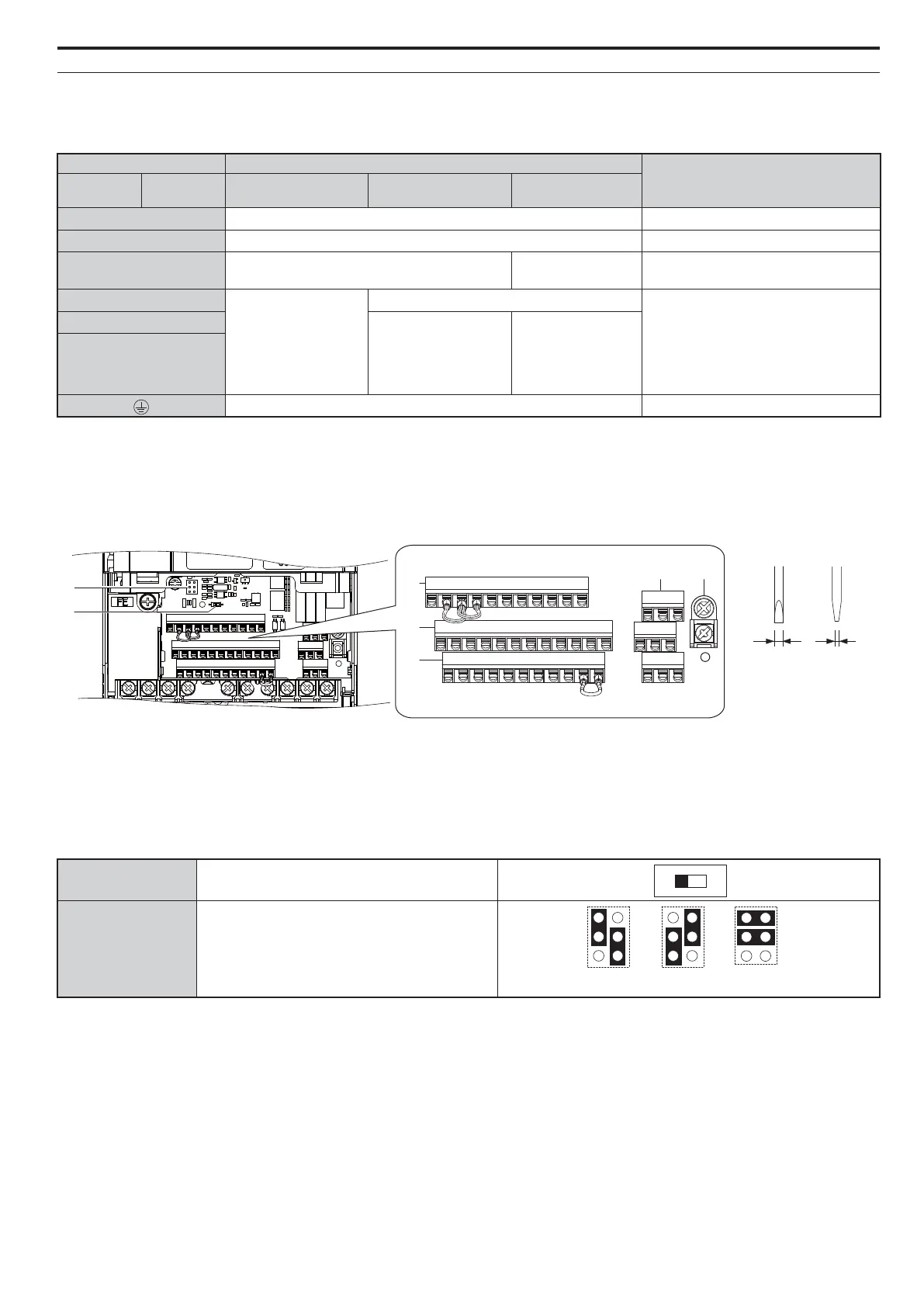
The figure below shows the control circuit terminal arrangement. The drive is equipped with screwless terminals.
DIP switch S2 and jumper S3 are located on the terminal board. Set them as described below.
Terminal Type
Function
400 V Class
Model
HPV1000
4009 to 4039 4045, 4060 4075 to 4216
R/L1, S/L2, T/L3
Main circuit power supply input Connects line power to the drive
U/T1, V/T2, W/T3
Drive output Connects to the motor
B1, B2
Braking resistor Not available
Available for connecting a braking
resistor or a braking resistor unit option
+2
• DC reactor connection
(+1, +2) (remove the
shorting bar between
+1 and +2)
• DC power supply
input (+1, –)
Not available
For connection
• of the drive to a DC power supply
(terminals +1 and – are not UL
approved)
• of dynamic braking options
+1, –
DC power supply input
(+1, –)
• DC power supply
input (+1, –)
• Braking unit
connection (+3, –)
+3
– Grounding terminal
A – Terminal Block (TB 2) E – Terminal Block (TB 4)
B – Terminal Block (TB 5) F – DIP switch S2
C – Terminal Block (TB 1) G – Jumper S3
D – Terminal Block (TB 3)
S2 RS422/485 Termination Resistor
S3
Safe Disable Input
Sink/Source/External Supply Selection
S1 S2 S3 S4 S5 S6 S7 S8 SN SC SP
M1 M2 M5
M3 M4 M6
MA MB MC
V+ AC V- A1 A2 FM AM AC P1 C1 P2 C2
E(G) HC H1 H2
DM+ DM-
IG R+ R- S+ S-
Use a straight-edge screwdriver
with a blade width of max 2.5 mm
and a thickness of max 0.6 mm to
release the terminals
V+ AC V- A1 A2 FM AM AC P1 C1 P2 C2
E(G) HC H1 H2
DM+ DM-
IG R+ R- S+ S-
S1 S2 S3 S4 S5 S6 S7 S8 SN SC SP
E
D
C
M1 M2 M5
M3 M4 M6
MA MB MC
A B
G
F
<(*
Source
External 24 Vdc
Power Supply
Sink