3 Electrical Installation
6 MAGNETEK HPV1000 AC Elevator Drive Technical Manual
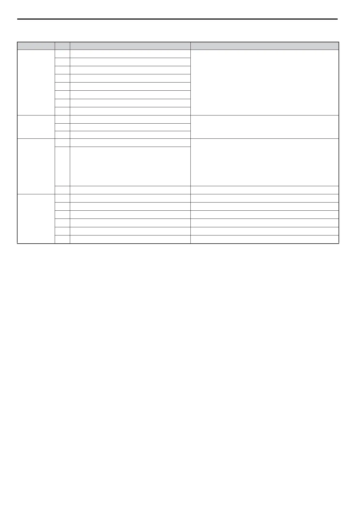
Control Circuit Input Terminal Functions
NOTICE: The wiring length to terminals HC, H1 and H2 should not exceed 30 m.
Type No. Terminal Name (Function) Function (Signal Level) Default Setting
Digital Inputs
S1
Multi-function input 1
Photocoupler
24 Vdc, 8 mA
Use the wire link between terminals SC and SN or between SC and
SP to select sinking or sourcing, and to select the power supply.
S2
Multi-function input 2
S3
Multi-function input 3
S4
Multi-function input 4
S5
Multi-function input 5
S6
Multi-function input 6
S7
Multi-function input 7
S8
Multi-function input 8
Digital Input
Power Supply
SC
Multi-function input common
Photocoupler, 24 Vdc, 8 mA
Use the wire link between terminals SC and SN or between SC and
SP to select sinking or sourcing, and to select the power supply.
SN 0 V
SP +24 Vdc
Safe Disable
Inputs
H1
Safe Disable input 1
24 Vdc, 8 mA
One or both open: Drive output disabled
Both closed: Normal operation
Internal impedance: 3.3 k∧
Off time of at least 1 ms
Set the S3 jumper to select sinking or sourcing, and to select the
power supply.
H2
Safe Disable input 2
HC
Safe Disable function common Common for the Safe Disable function
Analog Inputs
+V
Power supply for analog inputs 10.5 Vdc (max. allowable current 20 mA)
–V
Power supply for analog inputs -10.5 Vdc (max. allowable current 20 mA)
A1
Multi-function analog input 1 -10 to 10 Vdc, 0 to 10 Vdc (input impedance: 20 k∧)
A2
Multi-function analog input 2 -10 to 10 Vdc, 0 to 10 Vdc (input impedance: 20 k∧)
AC
Analog Input common 0 V
E (G)
Ground for shielded lines and option cards –