8 Appendix
MAGNETEK HPV1000 AC Elevator Drive Technical Manual 65
Zero Contactor Operation – EN81-20
Installation
The safe disable circuit can be utilized to install the HPV1000 drive in an elevator system with no motor contactor. In
such a system, the following guidelines must be followed to comply with EN81-20:
• The circuit must be designed so that the inputs H1 or H2 are opened and the drive output shuts off when the safety
chain is interrupted.
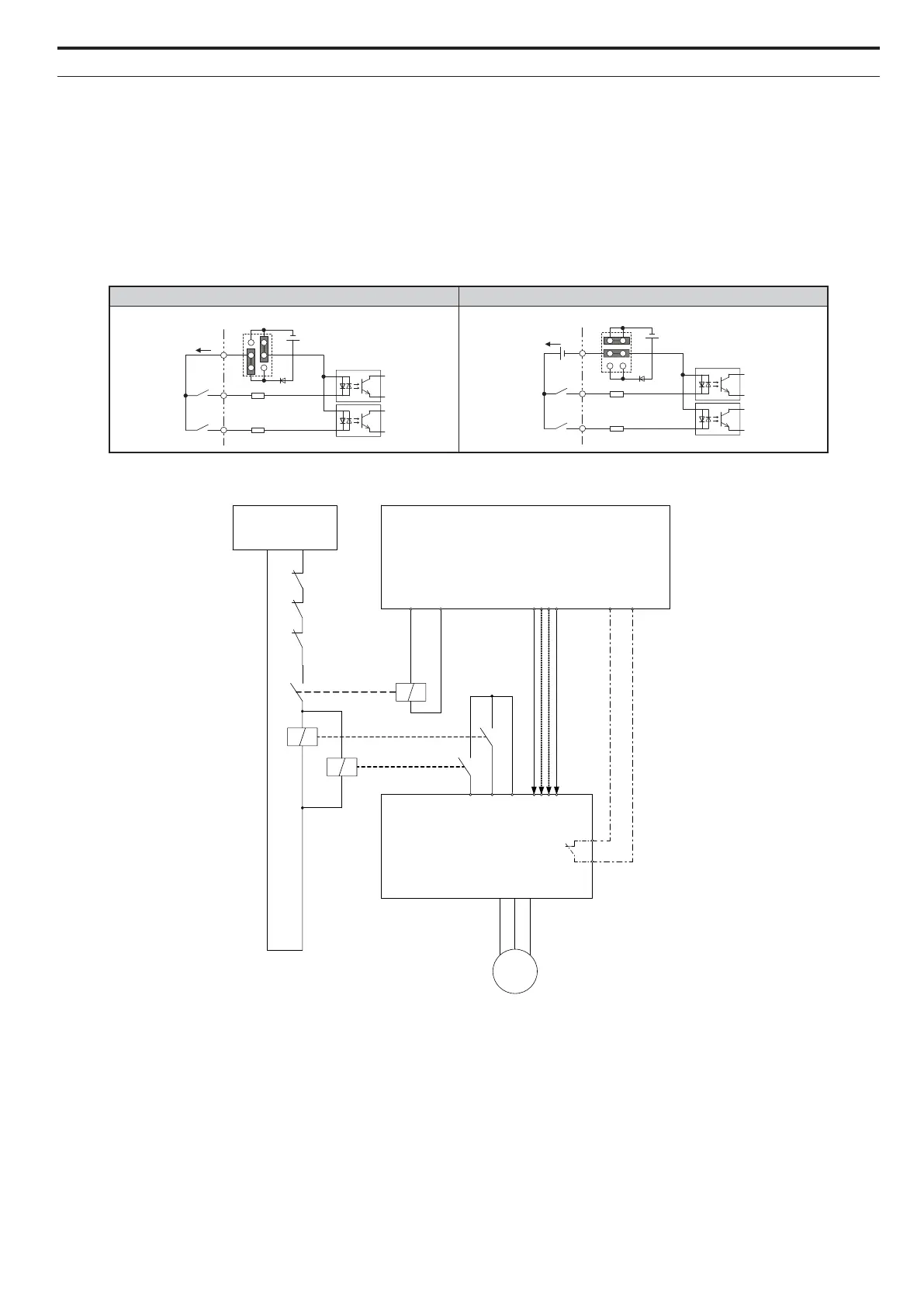
• The safe disable inputs H1 and H2 must be used to enable/disable the drive. The input logic must be set to Source
Mode, i.e. jumper S3 must be set like shown below.
The figure below shows a wiring example.
Note: 1. The drive output will immediately shut off when either of the inputs H1 or H2 is opened. In this case the brake should apply
immediately in order to prevent uncontrolled movement of the elevator.
2. Terminals H1 or H2 must be closed prior to setting the Up/Down command.
3. A drive logic output (C3) must be programmed as Safe Disable status. This feedback signal can be implemented in the contactor
supervision circuit of the controller that monitors a fault in the Safe Disable circuit.
Drive Internal Power Supply External 24 Vdc Power Supply
24 Vdc
H1
H2
HC
External
24 Vdc
Jumper S3
Safety Chain
Circuit
Elevator Controller
Drive Ready
Command
Status Monitor
K01
24 Vdc
K2
H2 H1
Safe Disable Monitor
(H2- = 58)
M
HC
Drive
K1
Up/Down;
Speed
selection; ...