6 Installation Startup and Autotune Guides
38 MAGNETEK HPV1000 AC Elevator Drive Technical Manual
Table 19
Power Up and Parameterization
Enter / verify the hoistway parameters:
• CONTRACT CAR SPD (A1) parameter should be the elevator contract speed in m/s.
• CONTRACT MTR SPD (A1) parameter should be set to an RPM that will make the elevator travel at desired car speed
(measured with hand tachometer).
Note: The above two parameters are utilized by the drive for many purposes regarding speed control of the lift, therefore it is important
these are set correctly.
Enter the Line Voltage in the A4 menu:
• INPUT VOLTAGE (A4) parameter should be set to the measured incoming phase to phase voltage.
When all connections and terminations are made, and the controller switched to ‘Test/Inspection Controls’ you can then
power up the installation. You will next need to verify the parameters entered in the drive match that of the motor data
plate, please do not assume that these are already entered correctly.
You may wish to note your motor data in the adjacent box for reference:
Note: Some motors do not quote the number of motor poles however this can be simply calculated using this formula:
Note: Ensure that the motor connections are phased correctly, that is U, V, W (A, B, C) terminals on the control panel terminal rail are
connected to the hoist motor terminals U, V, W.
The motor data obtained from the motor data plate should now be entered in the A5 menu of the drive. When this is
complete and the control system is prepared to run with any required wiring/links, etc. the encoder alignment can take
place.
In some instances the data on the motor data plate may not be 100% accurate (if the machine is not ‘made to order’ they
may quote the motors maximum values as opposed to what is required for your installation) - if this is the case the
‘calculated’ motor data that matches your installation will have to be obtained from the motor manufacturer and entered
in the drive. This ‘Calculated’ data may have been used to select the drive and the information on the data plate may be
beyond the rating of the drive. It is also important to verify and adjust the CONTRACT MOTOR SPEED parameter in
the A1 Menu of the drive at this stage.
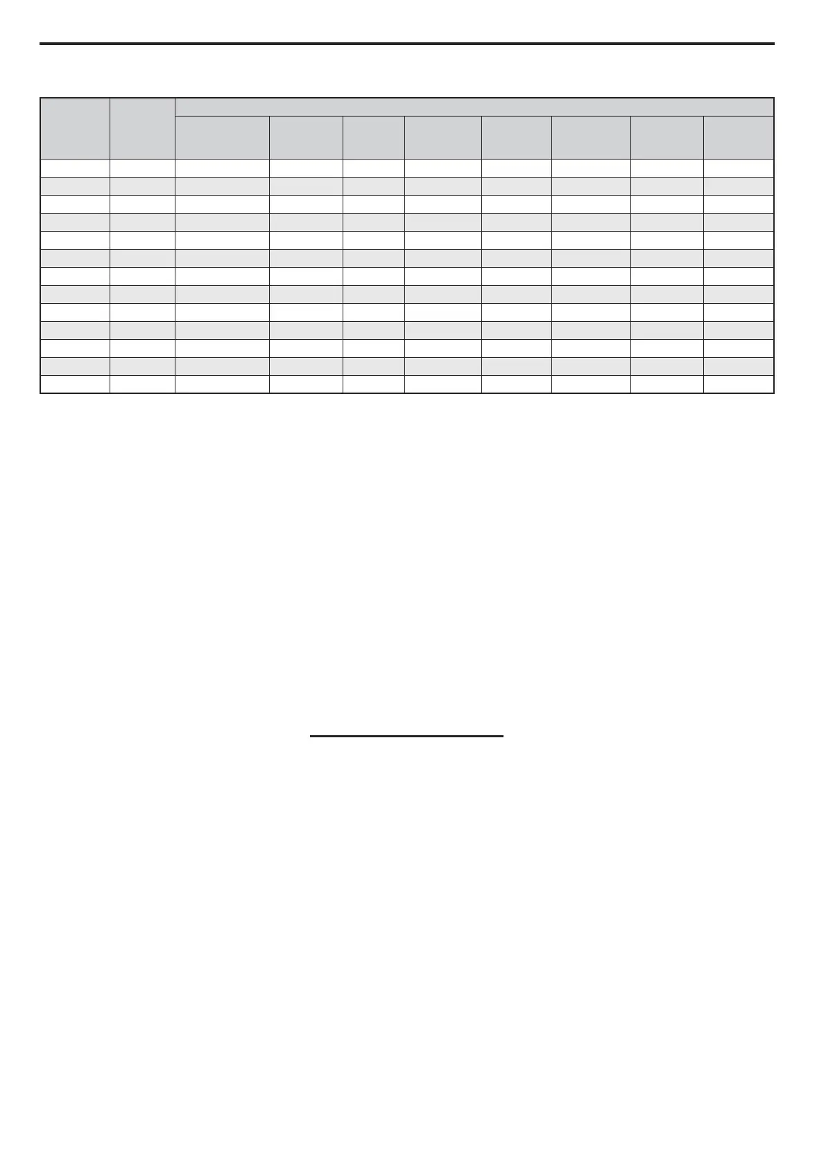
Encoder
Signal
PG-F3
Terminal
Cable Colours
Heidenhain Ziehl CEG
IME
Package
Extension
Wittur
Wittur 2
(Extension)
Sassi
ECN1313
Site
Encoder
A/ A- Yellow & Black Red & Blue Brown Purple Yellow Pink Purple
A A+ Green & Black Grey & Pink White Green Green Grey Red
B/ B- Red & Black Red Yellow Pink Pink Yellow White
B B+ Blue & Black Blue Green Blue Grey Green Brown
Data/ /DT Pink Brown Pink Brown White Brown Blue
Data DT Grey White Grey Grey Brown White Ye ll ow
Clock/ /CK Yellow Black Red White Black Purple Pink
Clock CK Purple Purple Blue Black Purple Black Green
0V Com IG Green & White Pink Purple Yellow Blue Blue Red & Blue
+5V IP Green & Brown Grey Black Red Red Red Grey & Pink
0V Sense IG White Yellow N/A N/A N/A N/A Black
+5V Sense IP Blue Green N/A N/A N/A N/A Grey
Shield FE Shield Shield Shield Shield Shield Shield Shield
120 x Rated Motor Frequency
Rated Motor Speed