Flex 4EX2 / 6EX2 MRX CE Instruction Manual
November 2018
Page 23 of 44
5. The Status LED displays current pushbutton function setting with orange, green and
red blinks. An orange blink represents the hundreds (+100), a green blink represents
the tens (+010), a red blink represents the units (+001), and solid orange represents
no function (000). For example, 1 orange blink followed by 2 green blinks and 5 red
blinks is pushbutton function no. 125. Pushbutton function number with “0” is
represented by no orange, green or red blink. For example, 1 orange blink followed by
5 red blinks is pushbutton function no. 105.
6. Set pushbutton function number by pressing PB3 to increment the hundreds (+100),
PB2 to increment the tens (+010), PB1 to increment the units (+001), and PB4 to reset
(000 - solid orange). For example, press PB3 one time, PB2 four times, and PB1 six
times for pushbutton function no. 146 (Status LED blinks 1 orange, 4 greens and 6
reds).
7. Exit Pushbutton Function mode by rotating the power switch key to OFF ( 0 ) position.
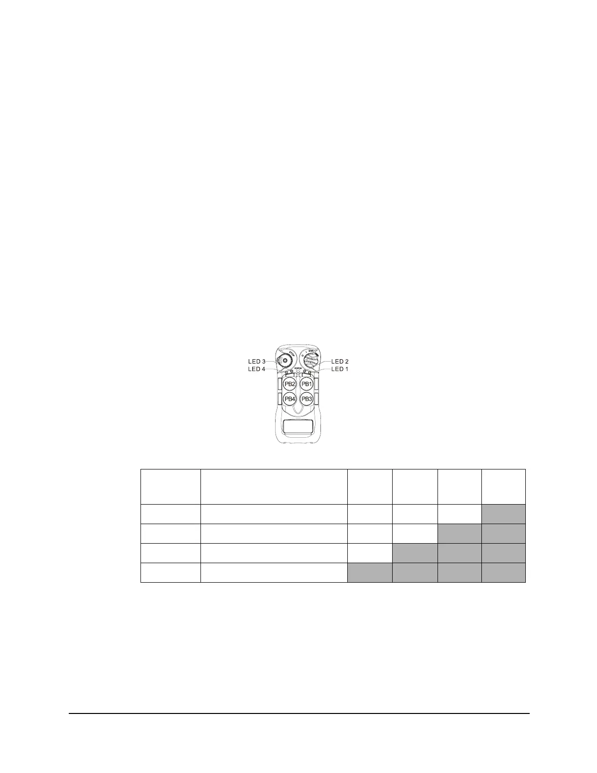
4.1.8.1 Toggled Pushbutton with LED Indication – Standard Right/Left
Pushbutton Configuration
Set pushbutton toggled function (latching output relay) with LED indications. LED 1 - 4
shown inside the shaded box illustrates which LED on the transmitter lights up when the
designated pushbutton is pressed.
4EX2:
* PB1...PB4 → Pushbutton number.
*Normal → Normal momentary contact.
* LED 1 - LED 4 → Pushbutton toggled function with designated LED indication.
Function
Number
Display Type PB1 PB2 PB3 PB4
1 1 Red Normal Normal Normal
LED 4
2 2 Reds Normal Normal
LED 3 LED 4
3 3 Reds Normal
LED 2 LED 3 LED 4
4 4 Reds
LED 1 LED 2 LED 3 LED 4