Flex 4EX2 / 6EX2 MRX CE Instruction Manual
November 2018
Page 34 of 44
5 Receiver Installation
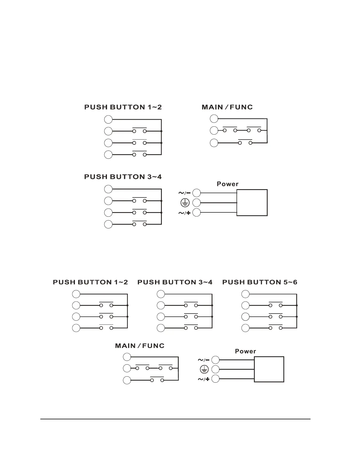
5.1 Output Relay Contact Diagrams
5.1.1 Flex 4EX2 (dual speed model)
* For 9-36VDC power supply, wire #1 corresponds to the negative charge (-) and wire #3 corresponds to
the positive charge (+). Wire #2 is for GROUND.
5.1.2 Flex 6EX2 (dual speed model)
* For 9-36VDC power supply, wire #1 corresponds to the negative charge (-) and wire #3 corresponds to
the positive charge (+). Wire #2 is for GROUND.
K1
9
COM
FWD
REV
F/R 2
11
10
8
K3
K2
FWD
12
K4
K5
13
REV
F/R 2
K6
14
8
COM
Power
Transformer
2
3
1
MAIN
COM
K27A
4
K27B
FUNC
7
K10
5
K1
9
COM
FWD
REV
F/R 2
11
10
8
K3
K2
FWD
16
K7
K8
13
REV
17
F/R 2
K9
18
15
COM
FWD
12
K4
K5
13
REV
F/R 2
K6
14
8
COM
Power
Transformer
2
3
1
MAIN
COM
K27A
4
K27B
FUNC
7
K10
5