Flex 4EX2 / 6EX2 MRX CE Instruction Manual
November 2018
Page 24 of 44
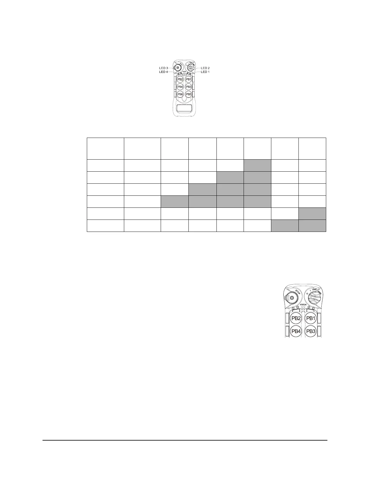
6EX2:
* PB1...PB6 → Pushbutton number.
*Normal → Normal momentary contact.
* LED 1 - LED 4 → Pushbutton toggled function with designated LED indication.
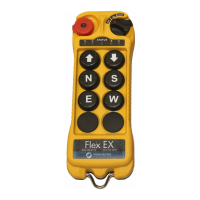
4.1.9 Display Frequency Band
1. Rotate the power switch key to OFF ( 0 ) position.
2. With the STOP button elevated, press and hold PB2 and PB4 at the
same time.
3. Rotate the power switch key to ON ( I ) position.
4. Release PB2 and PB4 at the same time. The system will enter
Frequency Band Display mode.
5. The Status LED displays the preset transmitter frequency band with
orange, green and red blinks. An orange blink represents the hundreds (+100), a
green blink represents the tens (+010) and a red blink represents the units (+001). For
example, 8 orange blinks followed by 6 green blinks and 3 red blinks is 863 MHz.
6. Exit Frequency Band Display mode by rotating the power switch key to OFF ( 0 )
position.
4.1.10 Output Feedback Settings
Up to 4 assignable relay outputs can be programmed into the system and feedback to
the transmitter LED indicators during operation. These settings require using the
infrared IR programmer unit. Please contact Magnetek field service for more details.
Function
Number
Display
Type
PB1 PB2 PB3 PB4 PB5 PB6
1 1 Red Normal Normal Normal
LED 4 Normal Normal
2 2 Reds Normal Normal
LED 3 LED 4 Normal Normal
3 3 Reds Normal
LED 2 LED 3 LED 4 Normal Normal
4 4 Reds
LED 1 LED 2 LED 3 LED 4 Normal Normal
7 7 Reds Normal Normal Normal Normal Normal
LED 2
8 8 Reds Normal Normal Normal Normal
LED 1 LED 2