Engineered XLTX Transmitter Instruction Manual
December 2016
Page 19 of 49
NOTE: If the shutdown sequence is started when the LED is not illuminated, the LED will stay in
the OFF state during the shutdown process.
NOTE: When the shutdown sequence is completed, all LEDs will turn off.
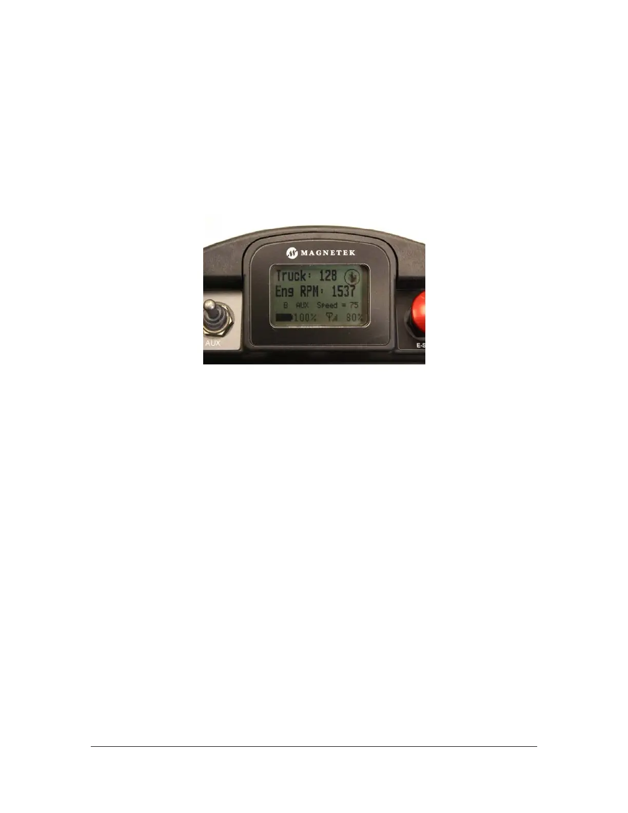
3.7 NORMAL OPERATING MODE WITH GRAPHIC USER INTERFACE
In normal operating mode, the XLTX displays real time information relating to the operation of the
transmitter on the graphic user interface. Information may include Command Confirmation,
Battery Life, Signal Strength, Two-Way Feedback, etc.
Figure 11: Normal Operating Screen on XLTX Graphic User Interface
3.7.1 Watch Dog Indicator (Spinning Arrow)
The spinning arrow represents the watch dog timer within the CPU of the unit.
NOTE: The arrow should be continuously spinning at all times. If the arrow is not spinning the
transmitter will need to be rebooted to operate properly.
3.7.2 Command Confirmation
Each time the user operates a control on the transmitter, a message will be displayed on the
graphic user interface screen confirming what is being operated.
For example, if the second paddle is moved to its 4
th
position in the UP direction the display will
show ‘MTN2 D1 SP=4’. This translates to ‘Motion 2, Direction 1, Speed 4’.
3.7.3 Battery Life Indicator
Remaining battery life is displayed in the bottom left hand corner of the graphic user interface
screen.
Battery life is displayed in 5% increments.
NOTE: If using a different battery pack than what the unit originally shipped with, the battery life
indicator will be inaccurate unless the dip switch settings are set to the correct battery type being
used. See Section 3.1.4 for details to properly set the dip switches.
NOTE: The battery display is only shown when the battery is powering the device. When the
device is powered through the optional tethered connection the battery indicator is not displayed
and a plug icon is display instead.
 Loading...