Engineered XLTX Transmitter Instruction Manual
December 2016
Page 22 of 49
Figure 12: Dip Switch Block as Viewed Through USB/IR Port
NOTE: The dip switch block switches are oriented so that the Off position is next to the number
designator and the On position is up or away from the number designator.
Regardless of which radio frequency the transmitter was equipped with the RF channel dip switch
settings are the same. Refer to Section 6.2 for details on the specific RF channel details for the
radio frequency that the transmitter is equipped with.
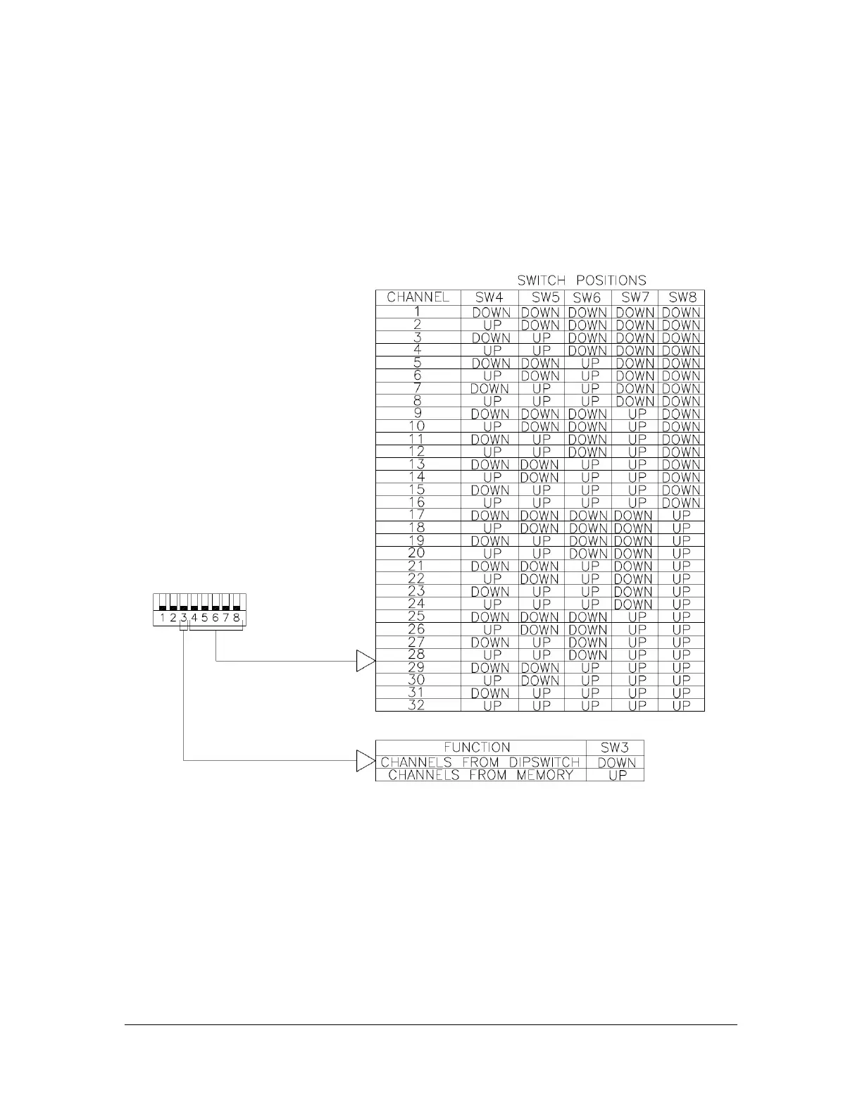
The following figure details the dip switch positions for each RF channel.
Figure 13: Dip Switch Positions for RF Channel Selection
The dip switch settings will take effect upon the next power cycle of the transmitter.
NOTE: If using the optional RCP software on transmitters NOT equipped with the graphic user
interface, the channel settings will read from the dip switch positions and not from memory when
the channel from memory override function is not enabled. The RF channel set by the optional
RCP software will not be used unless the memory override dip switch is set to ON. When the RF
channel from memory override is NOT enabled, the dip switch positions set the RF channel used
by the transmitter.
NOTE: If using the IR configuration receiver function on transmitters NOT equipped with the
graphic user interface, the channel settings will read from the dip switch positions and not from
memory when the channel from memory override function is not enabled. The RF channel set by