MOTORIZATION
20
647534EN
10 - 10/01/2017
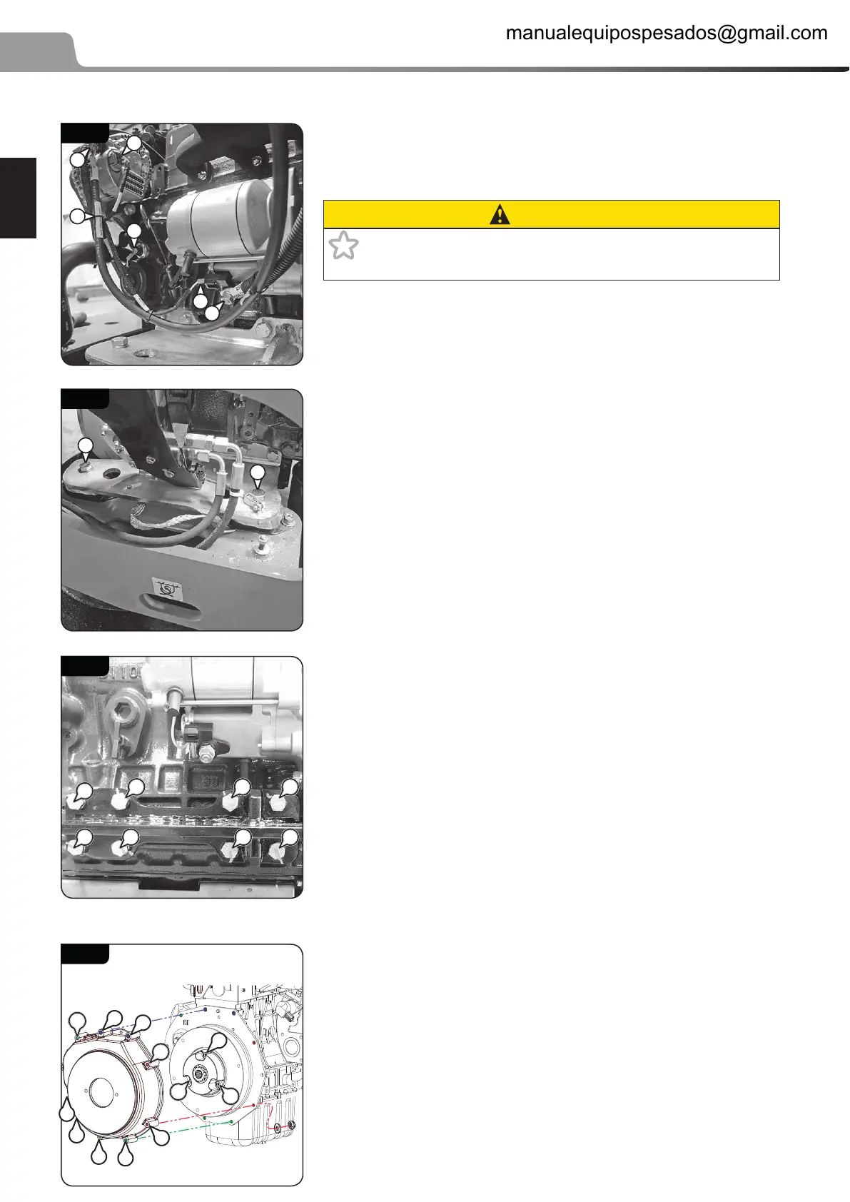
Cut the tie (1, 010 - 13).
Disconnect the alternator controller (2, 010 - 13) (AC102).
Disconnect the alternator power output cable (3, 010 - 13).
PRECAUTION
1 Battery cut-o: Cable connected to battery positive terminal,
disconnect the battery before handling.
Disconnect the oil pressure sensor (4
, 010 - 13) (DS100).
Disconnect the starter excitation (5, 010 - 13) (AC100).
Disconnect the starter power supply cable (6
, 010 - 13).
Undo the upper screw of the 4 left-hand and right-hand silent
blocks (1
, 010 - 14).
Pass a sling through the engine lifting rings and lift it out carefully
10.2.6 ENGINE REFIT
Proceed in reverse order to removal.
Adjust the position of the throttle valve (6ACCELERATOR VALVE
REFITTING, 5 18).
Ret the 2 ties near to the alternator and on the radiator air intake
hose.
2 Silent block center screw: 27 N.m (238.97 lb-in) ± 10%.
2 Exhaust support screw: 22 N.m (194.72 lb-in) ± 10%.
10.2.7 ENGINE CHANGE
2 Engine support bracket screws: 47 N.m (415.99 lb-in) ±10%
(1, 010 - 15)
2 Engine ywheel casing screws: 24 N.m (212.42 lb-in)±10% (1,
010 - 16).
2 Engine ywheel casing screws: 47 N.m (415.99 lb-in)±10% (2,
010 - 16).
2 Coupling screws: 20 N.m (177.01 lb-in)±10% (3, 010 - 16).
10 - 13
2
3
1
4
5
6
10 - 14
1
1
10 - 15
1 1 1
1111
1
10 - 16
1
1
1
1
3
1
1
1
2
2
3
3
manualequipospesados@gmail.com

 Loading...