MANITOWOC ENGINEERING, CO.
Division of The Manitowoc Company, Inc. Manitowoc, Wisconsin 54220
FLEXAI R VALVES
Maintenance and Adjustment
GENERAL
Flexair valves are primarily used to control the travel,
swing, boom hoist, and drum functions of the crane.
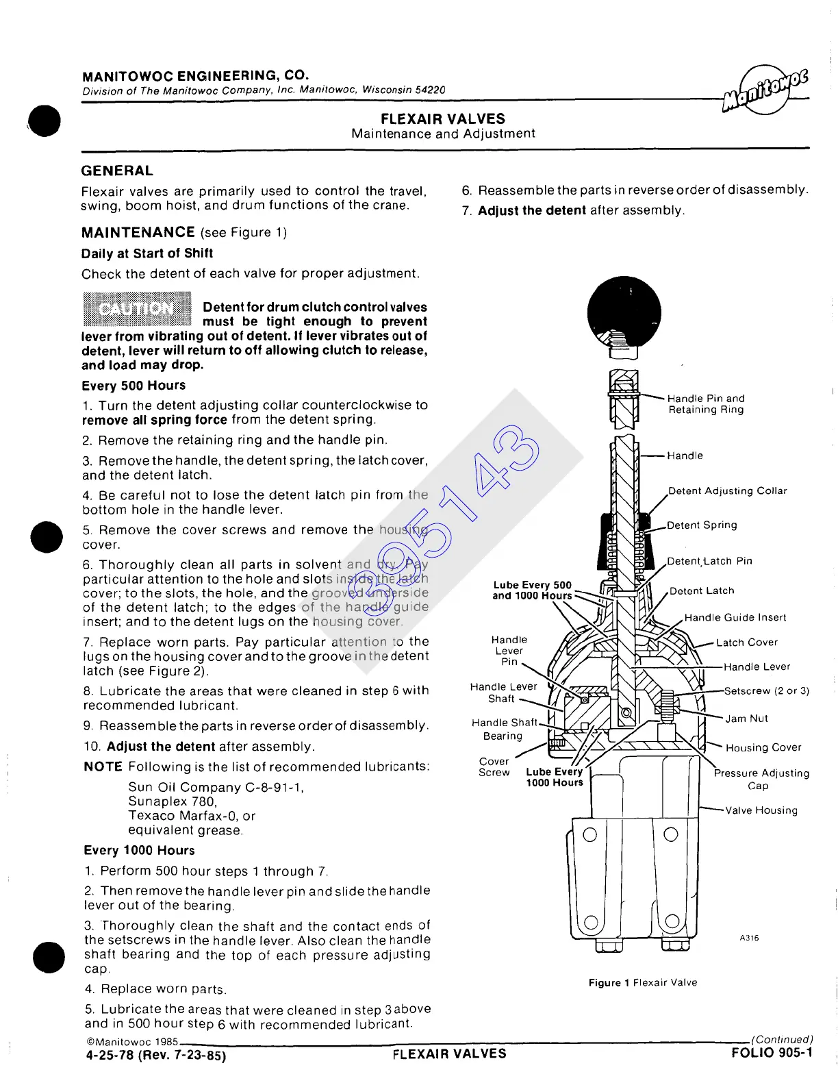
MAINTENANCE
(see Figure 1)
Daily at Start of Shift
Check the detent of each valve for proper adjustment•
ii~'~i~,~,~#!~i-~i~'~i':;::*~'~.:#:,~, ~!~~ !~"i i~ ~ ~ iiii~!~i!i
Detent for drum clutch control valves
must be tight enough to prevent
lever from vibrating out of detent. If lever vibrates out of
detent, lever will return to off allowing clutch to release,
and load may drop.
Every 500 Hours
1. Turn the detent adjusting collar counterclockwise to
remove all spring force
from the detent spring.
2. Remove the retaining ring and the handle pin.
3. Remove the handle, the detent spring, the latch cover,
and the detent latch.
4. Be careful not to lose the detent latch pin from the
bottom hole in the handle lever•
5. Remove the cover screws and remove the housing
cover.
6. Thoroughly clean all parts in solvent and dry. Pay
particular attention to the hole and slots inside the latch
Lul:
cover; to the slots, the hole, and the grooved underside
and
of the detent latch; to the edges of the handle guide
insert; and to the detent lugs on the housing cover.
7. Replace worn parts. Pay particular attention to the Han
lugs on the housing cover and to the groove in the detent Le~
Pi
latch (see Figure 2).
8. Lubricate the areas that were cleaned in step 6 with Handle
recommended lubricant. Shaf
9. Reassemble the parts in reverse order of disassembly. Handle
Beari
10. Adjust
the detent
after assembly•
NOTE
Following is the list of recommended lubricants:
Cover
Screw
Sun Oil Company C-8-91-1,
Sunaplex 780,
Texaco Marfax-0, or
equivalent grease.
Every 1000 Hours
1. Perform 500 hour steps 1 through 7.
2. Then remove the handle lever pin and slide the handle
lever out of the bearing.
3. Thoroughly clean the shaft and the contact ends of
the setscrews in the handle lever. Also clean the handle
shaft bearing and the top of each pressure adjusting
cap.
4. Replace worn parts.
5. Lubricate the areas that were cleaned in step 3above
and in 500 hour step 6 with recommended lubricant•
@Manitowoc 1985.,
4-25-78 (Rev. 7-23-85) FLEXAIR
VALVES
6. Reassemble the parts in reverse order of disassembly.
7. Adjust
the detent
after assembly.
•
Handle Pin and
~ Retaining Ring
liar
O
O
t
2
;ert
.~r
~ver
(2 or 3)
©
t-I--~J
Cover
Jjusting
using
A316
Figure
1 Flexair Valve
(Conhnued)
FOLIO
905-1
395143
 Loading...


