INSTALLATION
Reverse the removal steps and adjust the
controls.
positioner
Installing Converter Sprocket
INSTALLATION
Use LOCKTITE compound 40 (Loctite number 64041)
to secure the input sprocket to the converter input shaft.
Loctite compound 40 will reduce input spline wear.
REMOVAL
Evenly heat the sprocket to 250° F. Heat will reduce the
Loctite compound to powder and make sprocket remo-
val easier.
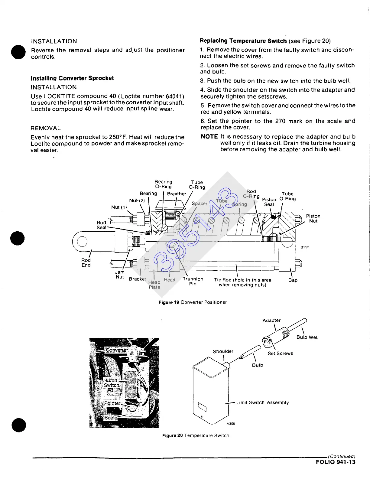
Replacing Temperature Switch
(see Figure 20)
1. Remove the cover from the faulty switch and discon-
nect the electric wires.
2. Loosen the set screws and remove the faulty switch
and bulb.
3. Push the bulb on the new switch into the bulb well.
4. Slide the shoulder on the switch into the adapter and
securely tighten the setscrews.
5. Remove the switch cover and connect the wires to the
red and yellow terminals.
6. Set the pointer to the 270 mark on the scale and
replace the cover.
NOTE It is necessary to replace the adapter and bulb
well only if it leaks oil. Drain the turbine housing
before removing the adapter and bulb well.
Rod
End
Bearing Tube
O-Ring O-Ring
Bearing Breather/ Ro.d Tube
• Nut'!2) / /'-~/"-~/ Spacer Tube u-,,ng Piston ()-Ring
Spring \ S T ,
./
Nut Bracket .. I . Head Trunnion Tie Rod (hold in this area Cap
I~ ~a~ e° Pin when
removing nuts)
Figure
19 Converter Positioner
Adapter /.~
~B u~l b Well
Shoulder ~ Set Screws
o,o
..L..--
Limit Switch Assembly
~A305
Figure 20
Temperature Switch
(Continued)
FOLIO 941-13
395143