MANITOWOC ENGINEERING, CO.
Division of The Manitowoc Company, Inc. Manitowoc, Wisconsin 54220
TORQUE CONVERTERS
All Models
CONTENTS Page
CONVERTER OPERATION ...................... 1
SYSTEM OPERATION
Controlled Converter .......................... 2
Non-Controlled Converter ...................... 2
MAINTENANCE CHECKS ........................ 4
MAINTENANCE PROCEDURES
Checking Converter Oil Tank Level ............. 5
Checking Output Housing Oil Level ............. 5
Checking Input Housing Oil Level .............. 5
Cleaning Orifice Filter ......................... 6
Cleaning Charge Pump Sediment Filter ......... 6
Checking Charge Pump Belts .................. 7
Draining and Refilling Converter Oil System .... 7, 8
Cleaning Suction Screen ....................... 9
Replacing Converter Oil Filter .................. 9
Draining and Refilling Output Housing .......... 10
Draining and Refilling Input Housing ............ 10
Adjusting Controlled Converter Controls ..... 10, 1 1
Installing Trunnion Pin Bushings ............... 12
Overhauling Converter Positioner ............ 12, 13
Installing Converter Sprocket ................... 13
Replacing Temperature Switch ................. 13
Troubleshooting ............................ 14, 15
CONVERTER OPERATION
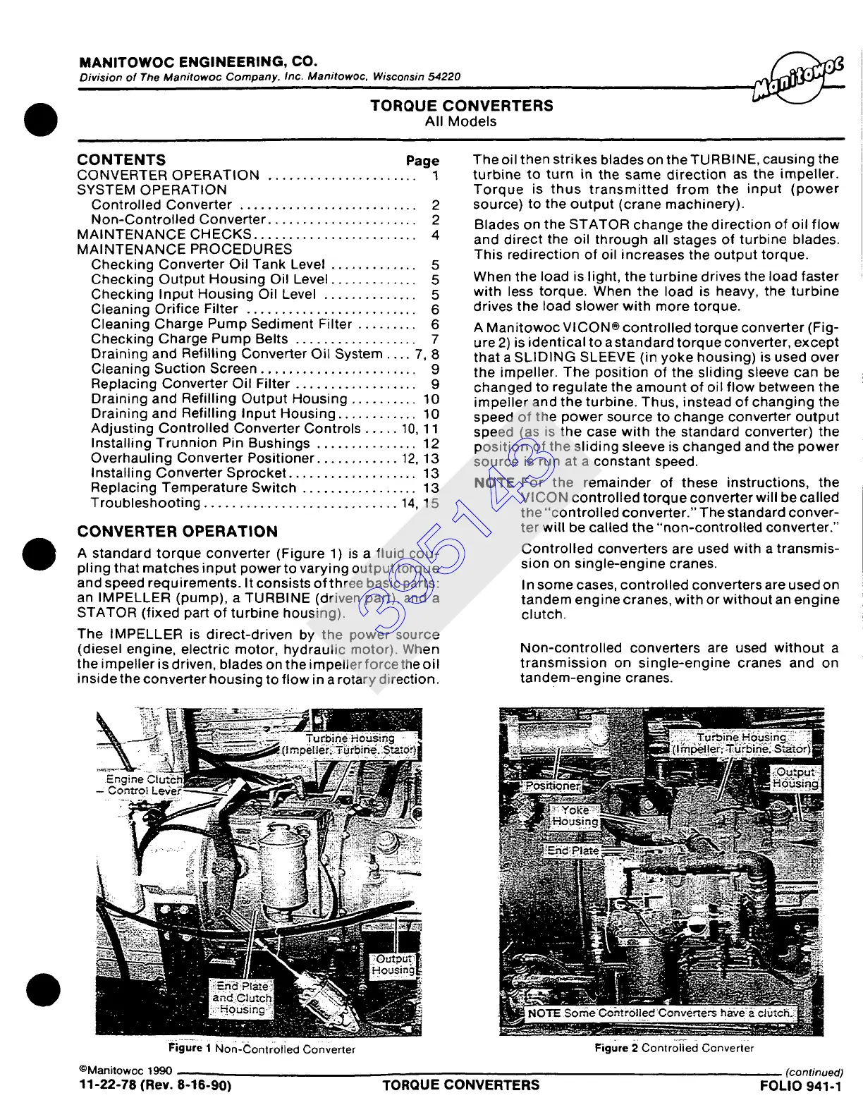
A standard torque converter (Figure 1) is a fluid cou-
pling that matches input power to varying output torque
and speed requirements. It consists of three basic parts:
an IMPELLER (pump), a TURBINE (driven part), and a
STATOR (fixed part of turbine housing).
The IMPELLER is direct-driven by the power source
(diesel engine, electric motor, hydraulic motor). When
the impeller is driven, blades on the impeller force the oil
insidethe converter housing to flow in a rotary direction.
The oil then strikes blades on the TURBINE, causing the
turbine to turn in the same direction as the impeller.
Torque is thus transmitted from the input (power
source) to the output (crane machinery).
Blades on the STATOR change the direction of oil flow
and direct the oil through all stages of turbine blades.
This redirection of oil increases the output torque.
When the load is light, the turbine drives the load faster
with less torque. When the load is heavy, the turbine
drives the load slower with more torque.
A Manitowoc VlCON® controlled torque converter (Fig-
ure 2) is identical to a standard torque converter, except
that a SLIDING SLEEVE (in yoke housing) is used over
the impeller. The position of the sliding sleeve can be
changed to regulate the amount of oil flow between the
impeller and the turbine. Thus, instead of changing the
speed of the power source to change converter output
speed (as is the case with the standard converter) the
position of the sliding sleeve is changed and the power
source is run at a constant speed.
NOTE
For the remainder of these instructions, the
VICON controlled torque converter will be called
the "controlled converter." The standard conver-
ter will be called the "non-controlled converter."
Controlled converters are used with a transmis-
sion on single-engine cranes.
In some cases, controlled converters are used on
tandem engine cranes, with or without an engine
clutch.
Non-controlled converters are used without a
transmission on single-engine cranes and on
tandem-engine cranes.
Figure i Non-Controlied Converter
©Manitowoc 1990
Figure 2 ControH-ed Converter
(continued)
11-22-78 (Rev. 8-16-90) TORQUE CONVERTERS FOLIO 941-1
395143