Draining and Refilling Output Housing
(see Figure 16)
On some converters, the output housing bearing is
either greased or lubricated by oil from the chain case.
When the output bearing is lubricated by either of these
methods, the output housing will not have a fill/brea-
ther/dipstick or drain valve.
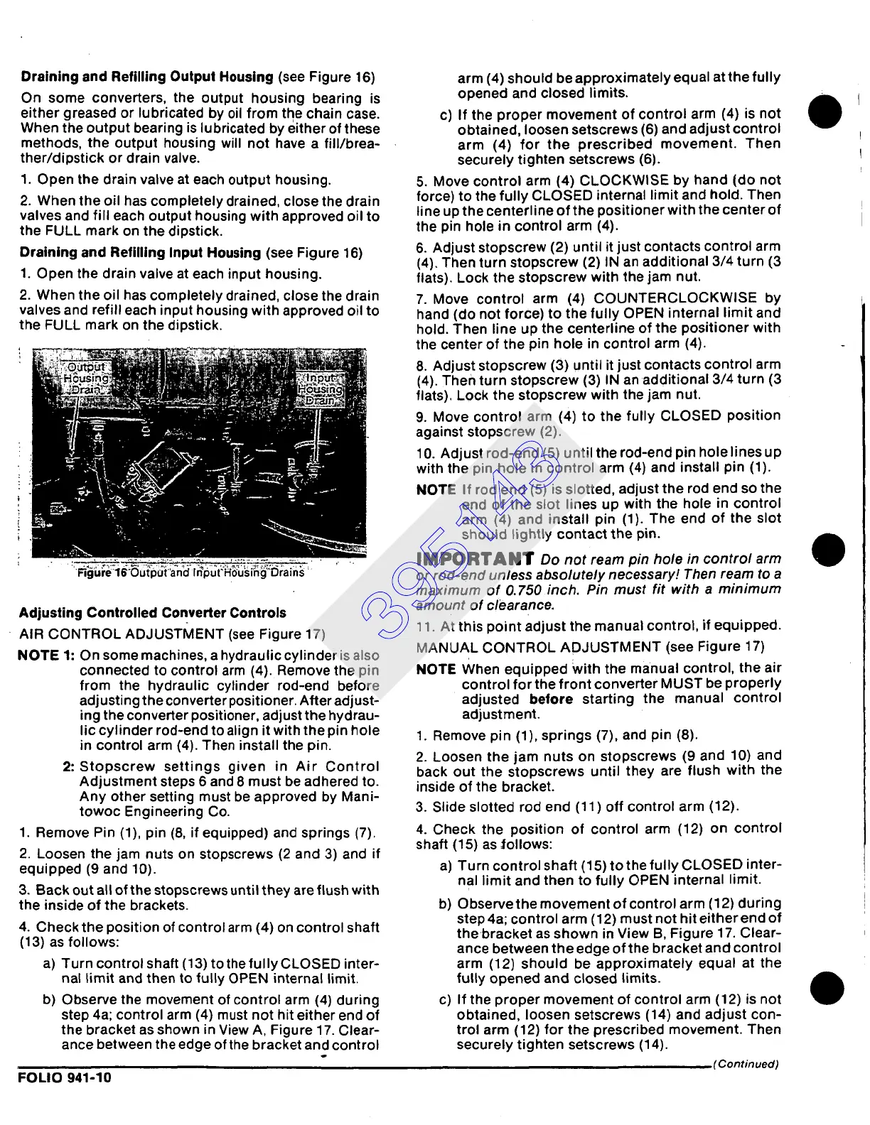
1. Open the drain valve at each output housing.
2. When the oil has completely drained, close the drain
valves and fill each output housing with approved oil to
the FULL mark on the dipstick.
Draining and Refilling Input Housing
(see Figure 16)
1. Open the drain valve at each input housing.
2. When the oil has completely drained, close the drain
valves and refill each input housing with approved oil to
the FULL mark on the dipstick.
r=gure]b-'uutp~Jt"ano mput'Hdusmg"urams
Adjusting Controlled Converter Controls
AIR CONTROL ADJUSTMENT (see Figure 17)
NOTE 1:
On some machines, a hydraulic cylinder is also
connected to control arm (4). Remove the pin
from the hydraulic cylinder rod-end before
adjusting the converter positioner. After adjust-
ing the converter positioner, adjust the hydrau-
lic cylinder rod-end to align it with the pin hole
in control arm (4). Then install the pin.
2:Stopscrew settings given in Air Control
Adjustment steps 6 and 8 must be adhered to.
Any other setting must be approved by Mani-
towoc Engineering Co.
1. Remove Pin (1), pin (8, if equipped) and springs (7).
2. Loosen the jam nuts on stopscrews (2 and 3) and if
equipped (9 and 10).
3. Back out all of the stopscrews until they are flush with
the inside of the brackets.
4. Check the position of control arm (4) on control shaft
(13) as follows:
a) Turn control shaft (13) to the fully CLOSED inter-
nal limit and then to fully OPEN internal limit.
b) Observe the movement of control arm (4) during
step 4a; control arm (4) must not hit either end of
the bracket as shown in View A, Figure 17. Clear-
ance between the edge of the bracket and control
FOLIO 941-10
arm (4) should be approximately equal at the fully
opened and closed limits.
c) If the proper movement of control arm (4) is not
obtained, loosen setscrews (6) and adjust control
arm (4) for the prescribed movement. Then
securely tighten setscrews (6).
5. Move control arm (4) CLOCKWISE by hand (do not
force) to the fully CLOSED internal limit and hold. Then
line up the centerline of the positioner with the center of
the pin hole in control arm (4).
6. Adjust stopscrew (2) until it just contacts control arm
(4). Then turn stopscrew (2) IN an additional 3/4 turn (3
flats). Lock the stopscrew with the jam nut.
7. Move control arm (4) COUNTERCLOCKWISE by
hand (do not force) to the fully OPEN internal limit and
hold. Then line up the centerline of the positioner with
the center of the pin hole in control arm (4).
8. Adjust stopscrew (3) until it just contacts control arm
(4). Then turn stopscrew (3) IN an additional 3/4 turn (3
flats). Lock the stopscrew with the jam nut.
9. Move control arm (4) to the fully CLOSED position
against stopscrew (2).
10.
Adjust rod-end (5) until the rod-end pin holelines up
with the pin hole in control arm (4) and install pin (1).
NOTE If rod end (5) is slotted, adjust the rod end so the
end of the slot lines up with the hole in control
arm (4) and install pin (1). The end of the slot
should lightly contact the pin.
|MPORTANT Do
not ream ph~ hole in control arm
or rod-end unless absolutely necessary! Then ream to a
maximum of O. 750 inch. Pin must fit with a minimum
amount of clearance.
11. At this point adjust the manual control, if equipped.
MANUAL CONTROL ADJUSTMENT (see Figure 17)
NOTE When equipped with the manual control, the air
control for the front converter MUST be properly
adjusted before starting the manual control
adjustment.
1. Remove pin (1), springs (7), and pin (8).
2. Loosen the jam nuts on stopscrews (9 and 10) and
back out the stopscrews until they are flush with the
inside of the bracket.
3. Slide slotted rod end (11) off control arm (12).
4. Check the position of control arm (12) on control
shaft (15) as follows:
a) Turn control shaft (15) to the fully CLOSED inter-
nal limit and then to fully OPEN internal limit.
b) Observe the movement of control arm (12) during
step 4a; control arm (12) must not hit either end of
thebracket as shown in View B, Figure 17. Clear-
ance between the edge of the bracket and control
arm (12) should be approximately equal at the
fully opened and closed limits.
c) If the proper movement of control arm (12) is not
obtained, loosen setscrews (14) and adjust con-
trol arm (12) for the prescribed movement. Then
securely tighten setscrews (14).
(Continued)
395143