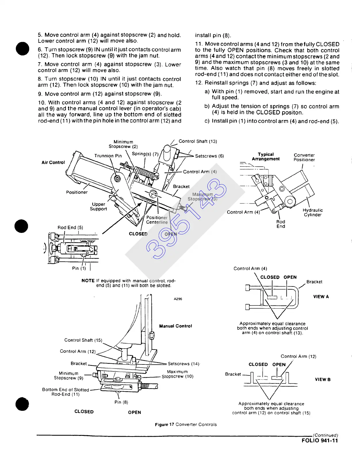
5. Move control arm (4) against stopscrew (2) and hold.
Lower control arm (12) will move also.
6. Turn stopscrew (9) IN until it just contacts control arm
(12). Then lock stopscrew (9) with the jam nut.
7. Move control arm (4) against stopscrew (3). Lower
control arm (12) will move also.
8. Turn stopscrew (10) IN until it just contacts control
arm (12). Then lock stopscrew (10) with the jam nut.
9. Move control arm (12) against stopscrew (9).
10. With control arms (4 and 12) against stopscrew (2
and 9) and the manual control lever (in operator's cab)
all the way forward, line up the bottom end of slotted
rod-end (11 ) with the pin hole in the control arm (12) and
install pin
(8).
11. Move control arms (4 and 12) from the fully CLOSED
to the fully OPEN positions. Check that both control
arms (4 and 12) contact the minimum stopscrews (2 and
9) and the maximum stopscrews (3 and 10) at the same
time. Also watch that pin (8) moves freely in slotted
rod-end (11 ) an d does not contact either end of the slot.
12. Reinstall springs (7) and adjust as follows:
a) With pin (1) removed, start and run the engine at
full speed.
b) Adjust the tension of springs (7) so control arm
(4) is held in the CLOSED positon.
c) Install pin (1) into control arm (4) and rod-end (5).
Minimum / Control Shaft (13)
Stopscrew (2) ~,"~
~'~ Trunnion Pin ~ Spring(s)(7)/N ~ Setscrews (6)
Typical
Converter
AirControl
/ ~"'"--.~ \ ,~\ / Lk...}/~ / = Arrangement Positioner
/ /
Control
Arm (4) Control A~~U
Positioner ~"~'- X 'k~ ~~"-Z Maximum
Stopscrew (3/
Upper & /
Support ~..~ //~" IXl~'~ lic
X~*J%'~'~ It ' | ~/\',,o~. "~'~/ Positioner ~ -- ~ L, ylmaer
J "~/ Centerline ~ Rod
Rod End (5) ~ - / ~ End
~/
1 ' / CLOSED OPEN
Pin 11) J
NOTE If equipped with manual control, rod-
end (5) and (11) will both be slotted.
r
- f l
C°nt r°l Arm (12) ~ '~,"~r )_1
Bracket ~..--~----~ ~ Setscrews (14)
Minimum ~ Maximum
Stopscrew (9) ~=~~~L~ Stopscrew (10)
Bottom End of Slotted ------~ ~
Rod-End (11) \
Pin (8)
CLOSED OPEN
Control Arm (4)
~ CLOSED OPEN
Approximately equal clearance
both ends when adjusting control
arm (4) on control shaft (13).
Bracket
VIEW A
Control Arm (12)
o
CLOSED OPEN/
Bracket
~J~.._~----~.~_ ~/./~ VIEW B
V
Approximately equal clearance
both ends when adjusting
control arm (12) on control shaft (15)
Figure
17 Converter Controls
(Continued)
FOLIO
941-11
395143